Proposed Way to Measure Flange
by Bill Donovan, Real Trains Inc
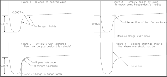
An issue I came up with is that the flange width (W) is measured from the back side of the wheel to a point where the other side of the flange intersects the gauging radius (R). This is a hard point to define, even using a cad system because you are dealing with the slope of the tread, the slope of the side of the flange and a radius between to locate this point. Add in the tolerances and it is really difficult. See figures 1 and 2.
My thought is to define the flange width at a point where the two flat surfaces would intersect inside of the gauging radius fillet. You could not measure this on a real wheel but in drawing if you only need to deal with the two straight surfaces. See figure 3.
Also an issue is that the drawings show a line where the side of the flange intersects the gauge (fillet) radius and measures to this point for the flange width (W). In current drafting standards there would not be a line here. Only a sharp (zero radius) edge or a surface perpendicular to the viewing plane would result in a line. The tangent point used is not one of these. See figure 4.
The main issue is the width of flangeways through frogs and the impact this would have on them since it would produce a slightly narrower frog with a smaller radius at the outer edge (r).
