Otha Hege Steam Turbine Generator
by Clyde Leonard
The Live Steamer, November 1951
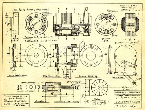
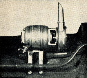
Otha Hege has gone and dood it again. He's turned out a little jewel of a turbine-generator unit. Copies will be furnished by Mr. Hege to L.S. readers on request, for a small fee, after he turns out a batch & figures the cost. He has built two of these little jiggers and take it from me, if they are built according to specifications, you have to use the right bulbs and number of them, or it'll snap them out fast.
Steam Turbo Generator in 3/4 Inch Scale
The Miniature Locomotive, November-December 1952
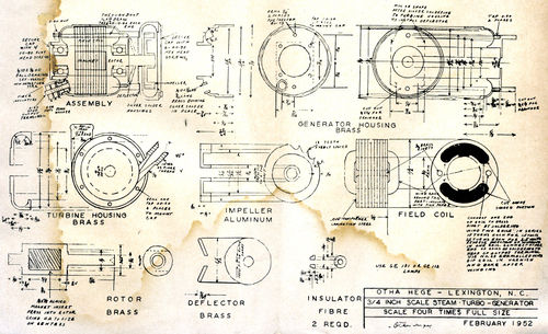
The rotor is made from either 7/16 inch or 1/2 inch round or square brass. The first operation is to put in the 1/4 inch by 3/8 inch rectangular hole through the material at right angles to the surface and at least 3/4 inch from the end. The simplest way to do this will be to drill two 5/32 inch holes through and file out to size. If preferable, a special tool can be made and the metal cut out to size in the shaper after first drilling to holes as before. A broach can be made which will simply be pushed through the material in an arbor press, the teeth cutting the hole to size. This hole should be one or two thousandths of an inch smaller than the magnet so that it will press in. Be sure the hole is in the center of the material, as the rotor will be out of balance if the magnet is not centered.
Put the material in the lathe and rough turn the outside diameter to about 0.390 inch, turn the end to 0.135 inch diameter for a distance of 9/16 inch, put a small center in the end and cut off 19/32 inch. Turn around in the 3 jaw chuck and turn the other end to 0.135 inch for a distance of 5/32 inch and center drill the end. Grind a shallow groove or niche on the 1/4 inch width of the magnet, all four corners. This is for the purpose of staking the magnet in place so that it cannot move. Press the magnet into place and roughly grind the ends of the magnet to the diameter of the brass. With a small center punch placed 1/32 inch from the niche in magnet and on the brass material, make four punch marks at the four corners of the magnet. This will swell the brass into the grooves and will hold the magnet securely in place. Put the rotor between centers, driving on the long end, and grind the large diameter to 0.365 inch with the tool post grinder, then turn the short end of the shaft to 0.125 inch for a light press fit in the bearing. The length of this end to be 5/32 inch. Reverse on centers and turn the other end to 0.125 inch for a distance of 9/16 inch.
The deflector is turned from brass with about a 25 degree taper on both the inside and outside, making it cone shaped. The outside diameter is 15/32 inch and the bore should be about 0.1245 inch so that it will be a light press fit on the rotor shaft. To ream this size hole, the flutes of a 1/8 inch reamer can be honed slightly making it undersize. The purpose of the deflector is to prevent any water which might condense in the turbine housing from being thrown out the clearance hole into the bearing in the generator housing.
The impeller is made from Duralumin. This can best be made in the milling machine with a dividing head, using a 3/64 inch radius cutter to form the teeth. In case you don't have a miller, they can be made in the engine lathe by the following method. Get two 180 degree protractors or one 360 degree, rivet this to a brass disc of the same diameter, then bore a hole so that this will slip over the lathe spindle behind the chuck. Fasten a wire to any convenient bolt head and flatten the other end to act as a pointer. Put the dural rod in the 3 jaw chuck, turn to 21/32 inch for a distance of 5/8 inch, then turn a 1/8 inch wide groove 1/16 inch deep, 1/2 inch from the end of the material. Grind a round nose tool 3/64 inch radius and place it in the tool holder on its side with the cutting edge toward the headstock, and at the proper height to form the teeth approximately as shown. Turn the chuck by hand to zero on the protractor. Crank the lathe carriage by hand, taking about 0.005 inch cut each time and stopping the tool in the 1/8 inch groove in the material. The depth of grooves for the teeth will be governed by the position of the tool, so it will be best not to go full depth until two or three teeth have been cut. For the second tooth, turn the chuck to a reading of 20 degrees on the protractor, etc, nothing the starting and finish position of the cross slide, so that all the teeth will be the same depth. After several have been cut, go back to the first and cut each tooth deep enough so that on the circumference there will be about 1/64 inch of material between the teeth. After all the teeth are cut, center drill, drill and ream to 0.1245 inch. Grind a square nose tool about 1/8 inch wide and undercut the face about 3/32 inch deep between the bore and the teeth. This will lighten the part and will reduce the chance of vibration in the finished assembly. Cut off 1/8 inch thick.
The generator housing is made of brass in two parts. The end which has the connection is bored 0.375 inch to a depth of 1/2 inch. With a 3/32 inch radius tool turn the inside out to a diameter of 25/32 inch for a depth of 11/32 inch, which forms the clearance in the housing for the coils. The first 3/16 inch depth is bored to 13/16 inch, which leaves a small step on the inside which clamps the field coil in place when the two halves are bolted together. The outside diameter is turned to 7/8 inch and the radius is formed with an outside radius tool coming in from the back, then cut off 15/32 inch long. This leaves about 1/64 inch to be faced off later when adjusting the end play of the rotor.
The other end of the generator housing is center drilled, and drilled No. 30 to a depth of 5/8 inch. Then bore this out to 0.375 inch for a depth 7/16 inch. Face the back of this bore about 0.010 inch deeper and 5/16 inch diameter so as to leave a small step near the outside so that the inner race of the ball bearing will clear. The other dimensions in this housing are the same as the other housing. After the outside has been turned to 7/8 inch diameter and the 1/8 inch radius is formed, but off to a length of 5/8 inch. Make a stub arbor in the lathe that this housing will ship on tightly, and bore the other end to 9/16 inch diameter and a depth of 5/32 inch. Turn the outside to 11/16 inch diameter.
The turbine housing is bored to 11/16 inch for a depth of 5/32 inch and drilled No. 30 to a depth of 5/16 inch. Form the 3/32 inch radius on the inside to 7/8 inch diameter. Form the 1/8 inch radius on the outside, and with a square nose tool go down the back side of the housing and turn the 9/16 inch diameter boss, then cut off 17/64 inch long. The housing can now be held in the drill press vise or bolted to a piece of steel in the lathe tool holder to drill the exhaust and steam nozzle holes with an end mill. The steam nozzle is turned and threaded 10-32 or finer thread and the back is turned to 1/8 inch to fit in the housing. The nozzle is drilled through No. 60 and is center drilled for a flange fitting. Cut this off about 1/2 inch long, as it will be turned later for clearance of the impeller. The exhaust bushing is turned to 7/32 inch outside diameter and drilled and tapped 10-32 for finer thread. Cut this off 1/2 inch long and file on an angle to approximately fit the diameter of the inside of the turbine housing. Put the long end of the generator housing and the turbine housing together and hold in place with a 1/8 inch bolt through the No. 30 holes in each part, put the exhaust bushing and steam jet in the place and silver solder around them as well as the joint between the two housings. Clamp this assembly in the shaper and cut the two flats between the two housings for the installation of the deflector. Drill a 1/8 inch hole at the bottom and file the rectangular drainage hole. Drill and tap the two 0-80 tie bolt holes and the six 00-90 holes for the turbine housing cap. Also drill the two 1/16 inch tie bolt holes and the four 00-90 for the cap in the other half of the generator housing. Make the cap for the generator housing and hold in place by the four 00-90 screws. Clamp this housing in the shaper and cut the cap end of the housing to 7/16 inch square leaving a flat surface for the insulator bushing. Drill a 5/32 inch hole for this bushing 5/32 inch off the center line of the two tie bolt holes. Make the bushing of brass, 5/32 inch outside diameter, 1/8 inch bore and 3/32 inch long. Put in place and silver solder. Make two thin brass washers 1/16 inch bore by 1/8 inch O.D. Make two insulating washers of fibre 5/32 inch O.D. by 1/16 inch bore, with a step 1/8 inch diameter and 1/16 inch long.
Before the coils are wound, some small pieces of thin sheet fibre or electrical fish paper should be put in the slots and on the ends, to insulate the wire and eliminate the chance of grounding the wire during winding. This can be tied in place with sewing thread. Use about six feet of No. 28 enameled wire. Solder one end to the 1/16 inch rivets in the lamination assembly. Hold the assembly in a small vise and loop each turn through the opening, place it around the pole piece and pull up firmly in place. Wind 15 turns around the first pole piece, then turn the assembly over and wind 15 turns around the other, but be sure to reverse the direction of winding in the last coil. If this is not done the voltage generated in each coil will balance out the other one and the output will be zero. Slip a short length of small insulating tubing over the wire and leave it over the jumper between the coils for protection, also tie another short length at the end of the winding. Tie the last turn of wire in place with sewing thread. Dip the coil assembly in Spar varnish and bake for 24 hours at about 200 degrees. After the baking is finished run a 3/8 inch reamer through the center by hand to clean out the varnish and clean the outside of the assembly so that the steel laminations will make a good ground connection to the housing.
Assembly
Press the bearing on the long end of the rotor shaft. Put the deflector plate between the generator and turbine housings and start the rotor shaft through this by hand. Make a hollow sleeve, drilled No. 30, 5/16 inch O.D. and about 1/2 inch long to place over the shaft in the turbine housing to take the thrust while pressing in place. Stand the housing assembly in the press on the hollow sleeve and press the rotor and bearing down in place. Slip a split spacer over the rotor shaft under the deflector, so that this will be spaced about 0.005 from the generator housing, when the rotor bearing is in place. Turn the assembly over on the hollow sleeve and press the impeller on the rotor shaft, spacing it about the center of the turbine housing, sighting through the exhaust connection. Put the bearing on the other end of the rotor shaft, put the end of the housing with the end cap in place on the bearing and hold in place with the two through bolts. Measure the end play in the rotor. Take the short end of the generator housing off and remove the end cap. Face off the square end of the generator housing off and remove the end cap. Face off the square end of the housing so as to allow about 0.002 inch to 0.003 inch end play. Place the field coil assembly in the housing with the output wire to the open end, cut the wire about 1/2 inch long and solder to the head of an 0-80 by 5/16 inch brass bolt. Assemble this bolt with the flat washers and insulating bushings in the output terminal bushing. It is wise to coat the bushings and head of the screw with varnish to prevent it loosening when attaching the wire to the outside. Place an 0-80 nut on the screw and tighten in place. Put the end of the generator housing back in place and tighten the nuts on the through bolts. Replace the end cap. The rotor should now turn perfectly free with a slight amount of end play. Connect the steam line through a globe valve to the output terminal and ground. Running on 60 to 80 pounds of steam pressure these units will light from four to six flashlight lamps.
Ian Wynd
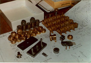
- Here is the photo showing the Ian Wynd disassembled turbogenerator and fixtures. His turbogenerator is a modified version of the original Otha Hege design for 3/4 inch scale.
- The mounting bracket, steam inlet and outlet flanges are all separate pieces which have been silver soldered to the turbine body. Form tools made from gauge stock were employed for machining the outer part of the turbine casing. The top plate in the picture (the lamination drill jig) is made from hardened steel and has 10 holes drilled in it as well as in the bottom plate. The two small stepped pins are used to flair the ends of the hollow tubes (rivets) to keep the laminations together. The flange with the hub to the left of the lamination drill jig is a center punch. The center hole was first punched out using 3/8 inch diameter drill rod made hollow and ground absolutely flat on its end. The OD of all the laminations for one unit, before rivetting together, were turned on a mandrel. All laminations were drilled together in the lamination drill jig after stacking (25 laminations). The bottom lamination after drilling always had burrs so to get around this problem, one more lamination was stacked than was necessary.
- A difficult part in the construction was the need to have tight fitting of the square magnets in the brass rotor. The magnets also have to have their poles across the axis of the rotor and not longitudinal to it.
References
- "Curtis Turbine Generator", Roland JF Evans, Live Steamer Magazine, November/December 1996
- "Steam Turbo Generator Part 1", Richard Chiapparelli, Live Steamer Magazine, September/October 1998
- "Steam Turbo Generator Part 2", Richard Chiapparelli, Live Steamer Magazine, November/December 1998


