Cylinders and Cylinder Heads for the Beginner's Locomotive
Cylinders and Cylinder Heads for the Beginner's Locomotive
An 0-4-0 Switcher of Simple Design in 3/4 inch Scale
Victoria Society of Model Engineers
The Miniature Locomotive, September-October 1953
We'll start off with a few words about eccentric straps. Drawings were in our May-June issue. The eccentric straps are cut from 1/4 inch sheet brass. Cut roughly to outline, drill the two bolt holes 9/64 inch, chuck and bore out to 1-1/16 for now. Saw in half, bolt together, rechuck and finish bore to fit the eccentric freely. You can always file a little off to take up slack but if it pinches sideways as they usually do you have to waste time scraping them. The bosses around the bolts should be rounded for neatness and the outside finished to shape.
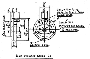
Drawing for Rear Cylinder Cover for Beginner's Locomotive.
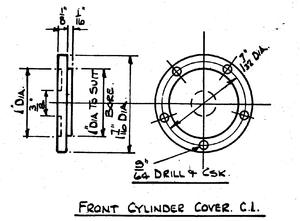
Drawing for Front Cylinder Cover for Beginner's Locomotive.
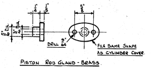
Piston Rod Gland for the Beginners Locomotive.


The eccentric rods are of 1/8 inch steel and fit into a step in the strap so they are flush with one side. Tin the mating faces and sweat them together. Drill two 3/32 inch holes and rivet with countersunk steel rivets (bits of welding rod). The pump strap is slotted and has the rod sandwiched between as there is not offset. Having fitted these up you can see the rocker arms wiggle when you push the chassis along with you'll feel you're getting somewhere.
We can now turn our attention to the cylinders. Chuck in the four jaws gripping by the sides and ends, valve face out, and cylinder flanges resting against the chuck body. Level up crossways so the valve face doesn't wobble and face off until the valve face is 1 inch from center of the cylinder found by taking half the diameter of the cylinder flanges, adding 1 inch and measuring this out from chuck face. Get the finish cut as smooth as you know how. Do both cylinders the same. Then turn them 1/4 turn bringing the bolting face outward. Set up as before but put a square against the chuck face and set the valve face to this to insure these two faces being at right angles to each other. Face off until this face is 1-3/8 inch from the cylinder center. Now mark one cylinder for each side and which is then to be gland end. This must be faced to the same setting when the cylinder is bored. You should put a 1/4 inch strip of steel under the chuck jaws to protect the faces, let these stick over the end 1/8 inch or so and it will be easy to set the cylinder in the right spot by calipering from the tail center to these strips and squaring from the chuck face up each cylinder face. Got it? Put a round nose tool in and face off the end until the flange is about 1/4 inch thick. The finished cylinder length is 2-1/4 inch so even it up. Now proceed to bore the cylinder. After a few cuts caliper it in case it's boring a taper. One corrective measure is to set the cutter upside down and bore on the back wall. As you get near size practice for a smooth surface. If you have a 1 inch reamer bore to 63/64 inch and ream by locking the lathe and turning the reamer with a spanner keeping the tail center in the reamer center at all times and not being too greedy on the feed. Another way is to bore to size, almost, and take the cylinder to a garage where they have a wrist pin honing machine. This will give a lovely true polished hole. I haven't a 1 inch reamer myself. To face off the front cylinder flanges it is quicker to just re-chuck, setting up by square only, as eccentricity of the bore matters not.

To mill the ports, I made a gang mill out of a piece of 1 inch drill rod. This has two 1/8 inch discs and one 1/4 inch disc in the middle with 1/8 inch groves between 1/4 inch deep. The stock was turned down to 5/8 inch for 1 inch back from the last ring. I then sawed a 1/4 segment out of it to form the cutting edge and filed the rest away leaving the discs only full diameter at the cutting edge. This was hardened and drawn until the yellow was only at the cutting edge (see Hardening and Tempering Colors) and it has milled the ports in ten cylinders so far without mishap. Of course you need a vertical slide or milling machine to use this. Three ports in twenty minutes is hard to beat. The connecting holes between cylinder bores and ports are two 1/8 inch holes at each end. File a little bevel to get a right angle start on the drill (see Drilling Steam Passages). Draw a line on the bolting face on the angle the connecting holes should be and when you're setting it in the drill vise set so this line is parallel to the drill. You should have no further trouble drilling the holes. Then bevel well away into the cylinder so the head spigot doesn't blind off the holes.
I had a pretty little marine engine once that wouldn't go at all just because the spigots blinded off the ports.
Now take the cylinder head and as the chucking piece which has to be tapered to draw out of the sand and most likely will be cockeyed needs trueing first, chuck in four jaw by outside, setting this to run fairly true and without wobble, then just clean up the chucking piece and face 1/16 inch off the cover leaving it 3/16 inch thick. Reverse, center up by the oval gland as we want uniform metal around this hole. Face off the gland to clean up only, center, drill 3/16 inch (being sure the drill doesn't wander) to a depth of about 5/8 inch. Open up with a 5/16 inch drill to within 1/16 inch of the inside of the head. Turn the outside to 1-7/16 inch diameter. Now with a a parting tool run in to the diameter of the cylinder bore leaving a spigot 1/16 inch deep to enter the cylinder. You have to use calipers here but try for a snug fit. You can remove from lathe and try easing with a file upon rechucking if its a little tight.
The front covers are just turned up the same O.D. and spigot sizes.
Each cover is held on by five No. 6 countersunk screws. One screw each side of the ports, one at the bottom and the other two will take care of themselves. With the back head screwed on, you can machine the guide bar seat. This must be parallel to the valve face both ways and 5/8 inch above the piston rod center. I have a German built lathe with the English type tool clamp which is very useful for holding a job when using a revolving cutter to machine such as this. American lathes with a vertical slide can do it but you may have to wait until you have the cylinder holding bolts tapped and can bolt the cylinder to a bar held in the tool post and use a fly cutter in a boring bar held in the chuck. Milling machine owners will be in clover, but it can be filed.
Turn up a gland from brass rod filing the flange oval to match the cylinder head. Drill 9/64 inch for glad screws. Clamp into the head with a 3/16 inch bolt through the piston rod hole, level up, spot the holes with 964 inch drill, then drill and tap No. 6-32. Screw in bits of No. 6 screw and cut off long enough to give a full nut when the gland has entered about 1/16 inch. You should make nuts of 3/16 inch hex for neatness sake. The gland should be tinned with solder to look like cast iron as I've never seen a full size locomotive with a brass gland. File the cylinder flanges down to the head size so the lagging plate will fit evenly. This fits under the fancy head cover plates.
It will be as well to get the cylinder "holding on bolts" drilled and tapped so take a piece of flat bar about 2 inch wide and 5 inch long 1/4 inch or more thick. Set this on the frame flush with one side when it will stick over the other side 2 inches. Mark it up through the exhaust hole in the cross connection. Drill and bolt on with a 5/16 inch bolt. Now take the exhaust hold in the bolting face of the frame as center, scribe a vertical line 1-1/16 inch ahead and behind this center. You can now lay the engine on its back, the cylinder is now laid on the flat bar centered by the two lines which should just show at each end of the casting. Clamp to the flat bar and spot the three holding on bolt holes. Remove, drill and tap 1/4 inch by 20. Swing the flat bar to the other side and do the other cylinder the same. Bolt on one cylinder at a time with 1/4 inch by 5/8 inch Allen cap screws and spot the steam and exhaust holes. Remove, drill the exhaust to meet the milled port and the steam to come up in the corner of the valve chest. That is, you drill in 9/16 inch and drill down to meet it. She's beginning to look like an engine now.