Drive Wheels Rods for the Beginner's Locomotive
Drive Wheels Rods for the Beginner's Locomotive
An 0-4-0 Switcher of Simple Design in 3/4 inch Scale
Victoria Society of Model Engineers
The Miniature Locomotive, May-June 1953
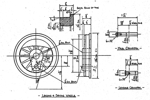
Now you'll want to turn the drivers, so chuck each by the tire with the front side out. A four jaw independent chuck is best for this job, if you want to be meticulous, however, the three jaw universal chuck is much faster and in most cases the castings can be made to run fairly true by a little experimenting. The inner side of the rim is all that needs be watched as the rest will be machined.
If your lathe is equipped with stops for the carriage so much the better. If not, a small "C" clamp and a short piece of soft brass will serve the purpose. Clamp the brass to the lathe bed in such a way that it will stop the carriage at the proper distance to face the tire. Then add 1/8 inch and you have the setting to face the crank boss and counter balance. A round nose tool is all that will be needed and it should be held in such a position to allow for cutting the tire as well as the facing cuts. Turn the tire first, leaving the diameter about 1/64 inch large (to be finished later between centers after the wheels are pressed on the axles). Then by use of the stops face the tire or wheel rim and also the crank boss and counter balance to finish dimension. Center drill and drill 3/8 inch for axle, open out with boring tool and ream 7/16 inch to finish size. Follow the same operations for all four wheels.
Reverse the wheels in the chuck and turn the back side. Since these are also facing cuts, use carriage stops same as before. Face the rim and wheel hub to correct finish dimension and clean up the spokes on the back side, if you wish. It won't make any difference in the operation of your locomotive if the counter-balance is faced off the same as the spokes on the back side.
All of your wheels should now be exactly alike. For the sake of beginners, not too familiar with the lathe work, it might be well to add that each of the cuts described is a finish cut and several cuts should be made first, leaving the last one, when the carriage is against the stop, very light. Another important point to remember is the radius between flange and tire. This is very important and does most of the work of steering the engine. If it is omitted or is too small there is a danger of derailment and it will also cause the engine to drag on curves.
We'll need a simple lathe fixture to drill the crank pin holes in the wheels. A piece of 1/4 inch steel plate 2 inch square or round, will do. Mark the centers for axle and crank pin and drill both holes 1/4 inch straight through. Now make a special bolt or stud having a 1/4 inch thread on each end, the shank being a nice push fit in the axle hole in the drive wheel and 1/2 inch long. Bolt the stud tight to the plate and hold the fixture in the four jaw or bolt to face plate so that the crank pin hole runs concentric. Scribe a center line on the crank boss of each wheel and align with tail stock center when they are pushed on the jig in the lathe. Clamp with nut and washer on the outer end of the stud, center drill, drill 3/16 inch, bore and ream 1/4 inch. Just let the reamer point come through. This will leave the end of the hole tapered. On an engine this small cold rolled steel will do for crank pins. File the ends in the lathe to match the taper in the wheel and the pin will fit snug enough in the rest of the hole.
Cut the axles a good 1/16 inch too long, center each end with a 3/16 inch pilot drill size. Mount between centers and face off the ends, then turn to press fit in wheels. The axle will protrude 1/32 inch through the wheel boss. You don't need "mikes" to get wheels to fit properly. Keep trying a wheel until it will just start on. Make sure it is parallel then eas the end of the axle with a fine file until the wheel can be wormed on, by hand, about halfway. This your fit and it won't slip or split the wheel.
The back to back spacing of the wheels is 3-5/32 inch which allows 1/32 inch end paly on the engine.
When both axles have been brought to this pint lay them aside and make the eccentrics. They'll be needed before we can do more assembling.
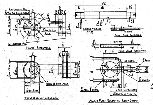
These are turned from bar, cast iron preferred, but steel would to. The center one carries the stop ins that drive the valve eccentrics. Let the stock stick out about 2-1/2 inch from the chuck, turn on 1-1/4 inch diameter. Set it over 3/16 inch in the churck so that when it is nearest the tool point is just touches, turn it half turn and a bit of 3/8 inch steel should just slip in between tool point and the eccentric blank. Face, center, drill and ream 1/2 inch.
Turn the hub ont he end of what will be a valve eccentric. This hub should be 5/16 inch long so that the total eccentric assembly will just fit between the axle boxes. Allow 7/8 inch for the eccentric plus the width of the parting tool and turn the hub of the next eccentric. Set the eccentric blank running true again and turn the grooves for the straps 1-1/8 inch diameter and the hub to be later cut away for the stops also 1-1/8 inch diameter and 3/16 inch long. The center eccentric is the same as the valve eccentric less the hubs or 3/8 inch thick only. Before you part them off mark the highest point of the eccentric on each one.
Drill the pump eccentric for a 3/16 inch allen set screw. Each side of this are the two stop pins. They are 1/2 inch out from the axle center and must be ninety degrees apart to match the crankpins. Drill and tap them 3/16 inch by 32 threads per inch.
The drawing is made as looking at the engineer's side of the engine and with the high side of the eccentric back of the axle. The stop pin for the right hand side is screwed into the top hole then walk around to the fireman's side and screw the left hand pin into the bottom hole.
That is the way the eccentric must go for a right hand lead engine. When running ahead the right hand crank passes the front center first, the left hand crank crossing ninety degrees later in the revolution.
On the valve eccentric nearly half the hub on the 1-1/28 inch diameter side is cut away. To do this scribe a line across the hub ninety degrees to the major axis center line and at 1/4 inch from the axle center.
Saw and file away this portion of the hub which will just be paper thick over the shaft hole. Break it away now lest it flake out later.
You can now do some putting together. The main thing to save time here is to take your time and make no mistakes. Oil the wheel seat of the driver you are going to put on the back or main axle on the engineer's side and press it on using the bench vise. When the axle is nearly in slip a 1/2 inch washer between the wheel and vise jaw to let the 1/32 inch extra axle stick through. Now face the engineer's side of the frame and drop the rear axle box on the axle and up to the wheel without turning it around. Put on one valve eccentric with the cut away portion towards the center of the engine. Then take the pump eccentric and with it in the position it is drawn, the high point to back and the upper stop pin facing you, pull it on the axle. Now comes the last eccentric with cut away on inside again, of course, and the other rear axlebox, again without turning. How take the rear driver, oil the wheel seat and start it on the axle.
Stand the wheels on a surface plate. Haven't got one, eh? Neither have I! So I just use a piece of car door window glass. Twist the wheel around until the crank on the engineer's side is forward on dead center the one on the fireman's side is at the top by eye. Check the flange diameter and take one-half of it.
This should be 1-5/8 inch and as the crank pin is 1/4 inch diameter a piece of 1-1/2 inch wide steel with the crankpin resting on it will set it on the dead center while you try a square up against the side of the other crankpin. Where it passes the axle center the square should be 1/8 inch or half the crank pin diameter away from the axle center. Twist the wheels until this applies, nothing very fussy needed. Push the wheel home and set it in the frames right way around. Now press on a leading driver, poke the axle through the axleboxes and start the other wheel on as before. Put the side rod on the side that's up and twist the loose wheel around until both crankpins are on the same side of the axles and both rest on the 1-1/2 inch steel strip at the same time, when the engine rests on the surface plate. Now slip on the other side rod. It should now be possible to turn the wheels without bind. If there is a slight bind find which way to turn the wheel a trifle until it's gone. Press the wheel a trifle until it's gone. Press the wheel home. I've done it many times myself and nary a miss. Set the wheels in the lathe again between centers and finish turn the tires to dimension and also shape the flanges. Face off the axle ends leaving only about 1/64 inch above the wheel. Remove to drill press, bring all the centers to the same size about 1/8 inch diameter of countersink.


