Building a Kitsap Caboose: Difference between revisions
| (23 intermediate revisions by the same user not shown) | |||
| Line 1: | Line 1: | ||
[[Category:Construction]] | [[Category:Construction]] | ||
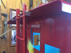
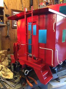
[[File:KitsapCaboose187.JPG|thumb|right|500px|Second test run of the Kitsap Caboose kit. It performed flawlessly. The battery box and air tank need to be painted red, and the remainder of the handrails are to be fabricated and installed. Note that the roof section has been removed to allow children to ride.]] | |||
by [[Daris A Nevil]] | by [[Daris A Nevil]] | ||
| Line 25: | Line 25: | ||
* Rustoleum ComfortGrip spray can handle and trigger | * Rustoleum ComfortGrip spray can handle and trigger | ||
* Red, White, Yellow and Black paint | * Red, White, Yellow and Black paint | ||
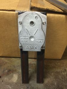
* | * [[Rivets|Rivet driver]] | ||
* Bucking bar (for [[Rivets|rivets]]) | |||
* Bucking bar (for rivets) | * 1/8 inch and 3/32 inch [[Rivets|rivets]] | ||
* 1/8 inch and 3/32 inch rivets | |||
* [http://www.harborfreight.com/30-in-bending-brake-61791.html Harbor Freight 30 inch sheet metal brake] | * [http://www.harborfreight.com/30-in-bending-brake-61791.html Harbor Freight 30 inch sheet metal brake] | ||
* [http://bondo.com/ Bondo body filler] | * [http://bondo.com/ Bondo body filler] | ||
| Line 41: | Line 40: | ||
=== Frame === | === Frame === | ||
<gallery widths="400px" heights="400px"> | <gallery widths="400px" heights="400px" perrow="2"> | ||
File:Kitsap Live Steamers Caboose 1.jpg|Laying out the base and other parts for the [[Kitsap Live Steamers]] caboose kit. Photo by [[Daris A Nevil]], April 2015. | File:Kitsap Live Steamers Caboose 1.jpg|Laying out the base and other parts for the [[Kitsap Live Steamers]] caboose kit. Photo by [[Daris A Nevil]], April 2015. | ||
File:Kitsap Live Steamers 2.jpg|The floor plates have been welded to the side beams. The center beam and bolster supports have been attached as well. The end beam has been welded to the end of the floor and the coupler pocket. The half rounds were previously brazed on the end beam. After looking at the prototypes closer I believe the end beam should have been turned around, with the flat facing out. It was difficult to tell from the drawings which way it was supposed to be mounted. | File:Kitsap Live Steamers 2.jpg|The floor plates have been welded to the side beams. The center beam and bolster supports have been attached as well. The end beam has been welded to the end of the floor and the coupler pocket. The half rounds were previously brazed on the end beam. After looking at the prototypes closer I believe the end beam should have been turned around, with the flat facing out. It was difficult to tell from the drawings which way it was supposed to be mounted. | ||
File:Kitasp Live Steamers Caboose 3.jpg|Top view of floor | File:Kitasp Live Steamers Caboose 3.jpg|Top view of floor plate showing "kiss marks" from "stitch" welds underneath. | ||
File:Kitsap Live Steamers Caboose 4.jpg|Bottom view of the floor shows stitch welds. These welds were made using a red Lincoln "tombstone" welder (seen under the table) with 1/8 inch 6011 rods. You must be very careful to prevent warping during welding, even with this thicker material. By careful I mean make short stitch welds (1/4 inch) and allow to cool between welds (10-15 seconds). Use lots of C-clamps to hold materials tightly together during welding. | File:Kitsap Live Steamers Caboose 4.jpg|Bottom view of the floor shows stitch welds. These welds were made using a red Lincoln "tombstone" welder (seen under the table) with 1/8 inch 6011 rods. You must be very careful to prevent warping during welding, even with this thicker material. By careful I mean make short stitch welds (1/4 inch) and allow to cool between welds (10-15 seconds). Use lots of C-clamps to hold materials tightly together during welding. | ||
</gallery> | </gallery> | ||
| Line 50: | Line 49: | ||
=== Body === | === Body === | ||
<gallery widths="400px" heights="400px"> | <gallery widths="400px" heights="400px" perrow="2"> | ||
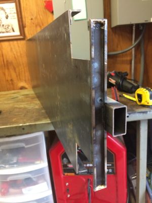
File:Kitsap Live Steamers Caboose 5.jpg|Angle iron has been stitched onto the end wall, which is now positioned for test fitting. I used small brass hinges for the doors, and brazed them to the steel. In retrospect I wish I had used rivets. | File:Kitsap Live Steamers Caboose 5.jpg|Angle iron has been stitched onto the end wall, which is now positioned for test fitting. I used small brass hinges for the doors, and brazed them to the steel. In retrospect I wish I had used rivets. | ||
File:Kitsap Live Steamers Caboose 6.jpg|Preparing for welding the four sides together. The clamps are from Harbor Freight, and were made for wood projects, but I found they worked quite well for this project (and I already had them). | File:Kitsap Live Steamers Caboose 6.jpg|Preparing for welding the four sides together. The clamps are from Harbor Freight, and were made for wood projects, but I found they worked quite well for this project (and I already had them). | ||
| Line 71: | Line 70: | ||
=== Roof === | === Roof === | ||
<gallery widths="400px" heights="400px"> | <gallery widths="400px" heights="400px" perrow="2"> | ||
File:KitsapCabooseBatteryBox8.jpg|The Kitsap kit ships with three roof sections: a long section, the roof for the cupola, and the short section behind the cupola. I wanted a removable roof so that small children can ride in the caboose, so I took the advice given in the instructions to cut the long roof section into two parts as shown in this photo. This is where the Milwaukee metal cutting circular saw came in handy. | File:KitsapCabooseBatteryBox8.jpg|The Kitsap kit ships with three roof sections: a long section, the roof for the cupola, and the short section behind the cupola. I wanted a removable roof so that small children can ride in the caboose, so I took the advice given in the instructions to cut the long roof section into two parts as shown in this photo. This is where the Milwaukee metal cutting circular saw came in handy. | ||
File:KitsapCabooseBatteryBox9.jpg|I used a low-cost sheet metal brake from Harbor Freight to bend all the roof sections. Here is the long roof section after | File:KitsapCabooseBatteryBox9.jpg|I used a low-cost sheet metal brake from Harbor Freight to bend all the roof sections. Here is the long roof section after cutting into two parts. This is the longest section and the hardest to bend in this jig. I used all the C-clamps I could round up. The bending operation worked smoother by spraying lubricant (WD-40) on the sheet metal where it was being bent. | ||
File:KitsapCabooseBatteryBox10.jpg|The short roof section cut from the long section has only about 3 inches of support to cling to. Three holes were drilled in the roof section on the left and right sides where it would sit on top of the roof beams. I first made stitch welds across the front of the caboose on the outside, underneath the roof section. You can see the "dots" of weld going up the photo. Then the six holes were fill welded with the wire welder, making sure the weld wire went all the way into the hole, attaching to the roof beam, and then filling the hole. The welds were ground flat with the roof. This resulted in a very strong roof section. | File:KitsapCabooseBatteryBox10.jpg|The short roof section cut from the long section has only about 3 inches of support to cling to. Three holes were drilled in the roof section on the left and right sides where it would sit on top of the roof beams. I first made stitch welds across the front of the caboose on the outside, underneath the roof section. You can see the "dots" of weld going up the photo. Then the six holes were fill welded with the wire welder, making sure the weld wire went all the way into the hole, attaching to the roof beam, and then filling the hole. The welds were ground flat with the roof. This resulted in a very strong roof section. | ||
</gallery> | </gallery> | ||
| Line 79: | Line 78: | ||
=== Battery Box === | === Battery Box === | ||
<gallery widths="400px" heights="400px"> | <gallery widths="400px" heights="400px" perrow="2"> | ||
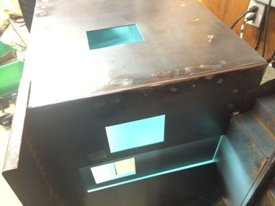
File:KitsapLiveSteamersCabooseBatteryBox.jpg|I decided to model the caboose after the Santa Fe caboose #999187 located at the [[Comanche & Indian Gap Railroad]] railroad. I needed a battery box in place of the tool cellar. Here my nephew Stephen is setting up to weld the box together. Note that this battery box was built from scratch, and is not part of the Kitsap Live Steamer's kit. | File:KitsapLiveSteamersCabooseBatteryBox.jpg|I decided to model the caboose after the Santa Fe caboose #999187 located at the [[Comanche & Indian Gap Railroad]] railroad. I needed a battery box in place of the tool cellar. Here my nephew Stephen is setting up to weld the box together. Note that this battery box was built from scratch, and is not part of the Kitsap Live Steamer's kit. | ||
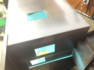
File:KitsapCabooseBatteryBox1.jpg|The dimensions of the box is 6-1/2 inches deep, 4-1/2 inches deep, and 3-3/4 inches high. After installation on the chassis the box looked a bit over-sized, so you may need to adjust for your taste. The battery box is large enough to hold a standard gel-cell battery. The battery will power the lights on the caboose. The two front braces were cut from 1/2 inch square steel tubing. It is cut down to about 1/8 inch high, so that the side ribs show prominently like the prototype. | File:KitsapCabooseBatteryBox1.jpg|The dimensions of the box is 6-1/2 inches deep, 4-1/2 inches deep, and 3-3/4 inches high. After installation on the chassis the box looked a bit over-sized, so you may need to adjust for your taste. The battery box is large enough to hold a standard gel-cell battery. The battery will power the lights on the caboose. The two front braces were cut from 1/2 inch square steel tubing. It is cut down to about 1/8 inch high, so that the side ribs show prominently like the prototype. | ||
| Line 92: | Line 91: | ||
=== Safety Chains === | === Safety Chains === | ||
<gallery widths="400px" heights="400px"> | <gallery widths="400px" heights="400px" perrow="2"> | ||
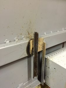
File:KitsapCabooseBatteryBox11.jpg|The instructions that came with the kit did not mention safety chains, so I had to decide where to attach the two chain hooks. I settled on welding a 1 inch by 1 inch steel angle on the center body beam, just behind the coupler attachment bolt. The eye bolts selected have long shanks, such that the eyes will be even with the end of the center beam. I later drilled holes for the eye shanks, but I wish I had drilled these holes before I welded the mount in place. | File:KitsapCabooseBatteryBox11.jpg|The instructions that came with the kit did not mention safety chains, so I had to decide where to attach the two chain hooks. I settled on welding a 1 inch by 1 inch steel angle on the center body beam, just behind the coupler attachment bolt. The eye bolts selected have long shanks, such that the eyes will be even with the end of the center beam. I later drilled holes for the eye shanks, but I wish I had drilled these holes before I welded the mount in place. | ||
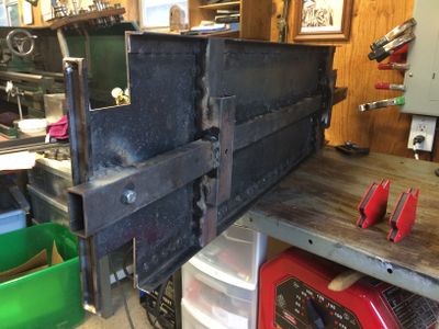
File:KitsapCabooseUnderframe.jpg|The underframe with primer paint. | File:KitsapCabooseUnderframe.jpg|The underframe with primer paint. | ||
| Line 99: | Line 98: | ||
=== Interior Paint === | === Interior Paint === | ||
<gallery widths="400px" heights="400px"> | <gallery widths="400px" heights="400px" perrow="2"> | ||
File:ValsparKoiPondSatin15310.jpg|Valspar "Koi Pond Satin", part number 15310, is a close match to the light green color found in many prototype cabooses. ([http://www.thenewsleaders.net/2013/03/28/ub222-sartell-man-keeps-alive-legend-lore-of-trains/ Take a look at the photos here.]) | File:ValsparKoiPondSatin15310.jpg|Valspar "Koi Pond Satin", part number 15310, is a close match to the light green color found in many prototype cabooses. ([http://www.thenewsleaders.net/2013/03/28/ub222-sartell-man-keeps-alive-legend-lore-of-trains/ Take a look at the photos here.]) | ||
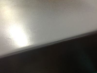
File:KitsapCabooseInteriorPaint.jpg|The caboose with a fresh coat of interior paint. This photo was taken with an iPhone in low light. The color is actually more green than the blue shown here. | File:KitsapCabooseInteriorPaint.jpg|The caboose with a fresh coat of interior paint. This photo was taken with an iPhone in low light. The color is actually more green than the blue shown here. | ||
| Line 106: | Line 105: | ||
=== Rounded Corners === | === Rounded Corners === | ||
<gallery widths="400px" heights="400px"> | <gallery widths="400px" heights="400px" perrow="2"> | ||
File:KitsapCabooseCorner1.jpg|The corners of the caboose are to be rounded (but not the corners of the cupola). This is accomplished by first filling the corners with Bondo, as shown here. | File:KitsapCabooseCorner1.jpg|The corners of the caboose are to be rounded (but not the corners of the cupola). This is accomplished by first filling the corners with Bondo, as shown here. | ||
File:KitsapCabooseCorner2.jpg|The corner is rounded by sanding. I used a grinder with an 60 grit sanding disk. Use gentle pressure and take your time. | File:KitsapCabooseCorner2.jpg|The corner is rounded by sanding. I used a grinder with an 60 grit sanding disk. Use gentle pressure and take your time. | ||
| Line 120: | Line 119: | ||
=== Mounting Brackets === | === Mounting Brackets === | ||
<gallery widths="300px" heights="300px"> | <gallery widths="300px" heights="300px" perrow="2"> | ||
File:KitsapCabooseAirTankBracket.jpg|The air brake reservoir is supported by a section of 1/2 by 1/2 inch angle steel welded on edge on the center beam. You should provide more space between the battery box and the reservoir bracket than shown here. | File:KitsapCabooseAirTankBracket.jpg|The air brake reservoir is supported by a section of 1/2 by 1/2 inch angle steel welded on edge on the center beam. You should provide more space between the battery box and the reservoir bracket than shown here. | ||
File:KitsapCabooseAirReleaseSwitchMountingBracket.jpg|A mounting bracket for the release switch from 2 by 2 inch steel angle, and welded to the edge of the underframe. | File:KitsapCabooseAirReleaseSwitchMountingBracket.jpg|A mounting bracket for the release switch from 2 by 2 inch steel angle, and welded to the edge of the underframe. | ||
| Line 127: | Line 126: | ||
</gallery> | </gallery> | ||
== Painting and Lettering == | === Painting and Lettering === | ||
The free program [https://inkscape.org/en/ Inkscape] was used to create [https://en.wikipedia.org/wiki/Scalable_Vector_Graphics SVG files] for all the vinyl lettering. The SVG files were then converted to [https://en.wikipedia.org/wiki/Encapsulated_PostScript EPS files] used by the Vinyl Cutter. All graphics (SVG and EPS) are included in the following Zip file: | |||
* [http://ibls.org/files/2015/KitsapCaboose/Vinyl_Decals.zip Vinyl_Decals.zip] | |||
<gallery widths="300px" heights="300px"> | |||
File:KitsapCabooseSprayPaint.jpg|I found this | <gallery widths="300px" heights="300px" perrow="2"> | ||
File:KitsapCabooseSprayPaint.jpg|I found this [http://www.vansicklepaint.com VanSickle] brand of enamel spray paint at a farm and ranch store named "Atwoods" in Greenville, Texas. Only the red and white was used on the caboose; yellow vinyl was used for the large "Santa Fe" logo instead. | |||
File:RustoleumComfortGripSprayCanPistolGrip.jpg|I highly recommend using a spray can pistol grip, such as this Rustoleum "Comfort Grip". This will help you make nice even coats of paint. | File:RustoleumComfortGripSprayCanPistolGrip.jpg|I highly recommend using a spray can pistol grip, such as this Rustoleum "Comfort Grip". This will help you make nice even coats of paint. | ||
File:KitsapCaboosePrimerPaint.jpg|The car body was removed to an outdoor table where it was sprayed liberally with "Easy Off Oven Cleaner" to degrease the surface before painting. The degreaser was | File:KitsapCaboosePrimerPaint.jpg|The car body was removed to an outdoor table where it was sprayed liberally with "Easy Off Oven Cleaner" to degrease the surface before painting. The degreaser was washed off thoroughly with water. Self-etching primer is then applied to the dry surface. The two different colors of primer resulted from running out of the gray and switching to a darker color. | ||
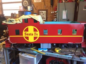
File:KitsapCaboosePaintedRed.jpg|The body has been painted red and is ready for further detail work. | File:KitsapCaboosePaintedRed.jpg|The body has been painted red and is ready for further detail work. | ||
File:KitsapCabooseCupolaNumber.jpg|A vinyl negative was cut and used as a paint mask for the large "187" on this side of the cupola. I used positive while vinyl letters on the other side, and they both turned out well. Note the addition of details, such as hand rails, ladder and brake wheel. | File:KitsapCabooseCupolaNumber.jpg|A vinyl negative was cut and used as a paint mask for the large "187" on this side of the cupola. I used positive while vinyl letters on the other side, and they both turned out well. Note the addition of details, such as hand rails, ladder and brake wheel. | ||
File:KitsapCabooseApplyingSantaFeLogo.jpg|Two large 10 inch diameter "Santa Fe" logos were cut from yellow vinyl. Masking tape was applied adjacent to the location of the logo. Black marks were located on the tape by measuring from the bottom of the chassis. These marks were used as aids when applying the logo to keep it "level". The application tape has not yet been removed from the logo. | File:KitsapCabooseApplyingSantaFeLogo.jpg|Two large 10 inch diameter "Santa Fe" logos were cut from yellow vinyl. Masking tape was applied adjacent to the location of the logo. Black marks were located on the tape by measuring from the bottom of the chassis. These marks were used as aids when applying the logo to keep it "level". The application tape has not yet been removed from the logo. | ||
File:KitsapCabooseYellowStriping.jpg|A 1/2 inch wide strip of yellow vinyl was applied after masking tape was | File:KitsapCabooseYellowStriping.jpg|A 1/2 inch wide strip of yellow vinyl was applied after masking tape was placed at intervals to aid in alignment. | ||
File:KitsapCabooseStepStripes.jpg|Narrow strips of white vinyl are applied to the top edge of each step for "safety". | File:KitsapCabooseStepStripes.jpg|Narrow strips of white vinyl are applied to the top edge of each step for "safety". | ||
File:KitsapCabooseRoadNameAndNumber.jpg|Road name and number applied on each side. If you haven't noticed already the caboose was numbered after the full size caboose at the [[Comanche & Indian Gap Railroad]]. | File:KitsapCabooseRoadNameAndNumber.jpg|Road name and number applied on each side. If you haven't noticed already the caboose was numbered after the full size caboose at the [[Comanche & Indian Gap Railroad]]. | ||
| Line 142: | Line 146: | ||
</gallery> | </gallery> | ||
== Brake Wheel == | === Brake Wheel === | ||
<gallery widths="300px" heights="300px"> | <gallery widths="300px" heights="300px" perrow="2"> | ||
File:HarryHaasSteelCabooseLiveSteamNovDec1995.jpg|A closeup of the brake wheel of Harry Haas' steel caboose featured on the cover of [[Live Steam Magazine]], November/December 1995. I used this basic design for the Kitsap caboose. | File:HarryHaasSteelCabooseLiveSteamNovDec1995.jpg|A closeup of the brake wheel of Harry Haas' steel caboose featured on the cover of [[Live Steam Magazine]], November/December 1995. I used this basic design for the Kitsap caboose. | ||
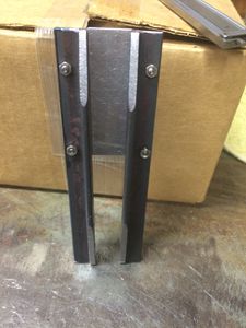
File:KitsapCabooseBrakeWheelStand.jpg|The brake wheel stand is cut from 1/4 by 1/4 inch angle steel. The bevels were cut on a mill. | File:KitsapCabooseBrakeWheelStand.jpg|The brake wheel stand is cut from 1/4 by 1/4 inch angle steel. The bevels were cut on a mill. | ||
| Line 150: | Line 154: | ||
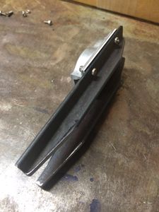
File:KitsapCabooseBrakeStandFront.jpg|The front side of the brake stand. | File:KitsapCabooseBrakeStandFront.jpg|The front side of the brake stand. | ||
File:KitsapCabooseBrakeStandFinished.jpg|The brake stand has been painted and installed. Four 5-40 by 3/4 inch bolts secure the brake stand to the bumper. | File:KitsapCabooseBrakeStandFinished.jpg|The brake stand has been painted and installed. Four 5-40 by 3/4 inch bolts secure the brake stand to the bumper. | ||
</gallery> | |||
== Hand Rails == | |||
<gallery widths="300px" heights="300px" perrow="2"> | |||
File:KitsapCabooseHandrail.jpg|I wanted a nice wide-radius curve on the handrails. I found a small pully with a groove that was perfect for 1/8 inch diameter steel rod. | |||
</gallery> | </gallery> | ||
| Line 156: | Line 166: | ||
* [http://kitsaplivesteamers.org/content.aspx?page_id=22&club_id=96970&module_id=149171 Kitsap Live Steamers S.P. Caboose webpage] | * [http://kitsaplivesteamers.org/content.aspx?page_id=22&club_id=96970&module_id=149171 Kitsap Live Steamers S.P. Caboose webpage] | ||
** [https://web.archive.org/web/20020407171348/http://kitsaplivesteamers.org/caboose.html 2002 Version of Caboose webpage, <i>Archive.org</i>] | ** [https://web.archive.org/web/20020407171348/http://kitsaplivesteamers.org/caboose.html 2002 Version of Caboose webpage, <i>Archive.org</i>] | ||
* [http://discoverlivesteam.com/2016/07/29/realistic-caboose-door-knob-on-the-cheap/ "Realistic Caboose Door Knob on the Cheap", <i>DiscoverLiveSteam.com</i>] | |||
Latest revision as of 16:55, 16 October 2016

November 2015
Equipment
- Kitsap Live Steamers caboose kit (check their website)
- Couplers
- Trucks
- Detail parts (most of mine came from Precision Steel Car)
Tools and Supplies
I hope this list of tools and supplies won't discourage you from tackling this kit. If you don't have one of the tools listed below then think about other ways you can accomplish the same operation with a different tool, or ask a friend that has the required tool to help you with that operation.
- Low-cost wire welder (110 Volt AC) from Harbor Freight
- Lincoln "tombstone" AC-225 welder (220 Volt AC)
- Lincoln Innershield NR-211-MP flux core welding wire, 0.035 inch
- Welding rods
- Harbor Freight drill press/mill
- Milwaukee 6370 Metal Cutting Circular Saw
- Self etching primer
- Rustoleum ComfortGrip spray can handle and trigger
- Red, White, Yellow and Black paint
- Rivet driver
- Bucking bar (for rivets)
- 1/8 inch and 3/32 inch rivets
- Harbor Freight 30 inch sheet metal brake
- Bondo body filler
- Harbor Freight 4 inch angle grinder
I started welding the kit using the Lincoln stick welder, which worked ok with the thick 1/8 inch steel floor. However, this could have been done with the wire welder as well, so you really don't need both welders. If you have to choose between the two then choose the wire welder.
I had no idea how to cut the 16 gauge roof steel (an operation step, see below). After doing some research and watching a YouTube video I decided to purchase a Milwuakee steel cutting circular saw. Wow, I'm so glad I did. This saw is such a joy to use. And the resulting cuts are so smooth and straight. It is as easy to use as a regular wood cutting circular saw. I know I will get many years of good use out of this tool.
Build Gallery
Frame
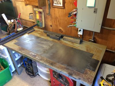
Laying out the base and other parts for the Kitsap Live Steamers caboose kit. Photo by Daris A Nevil, April 2015.
The floor plates have been welded to the side beams. The center beam and bolster supports have been attached as well. The end beam has been welded to the end of the floor and the coupler pocket. The half rounds were previously brazed on the end beam. After looking at the prototypes closer I believe the end beam should have been turned around, with the flat facing out. It was difficult to tell from the drawings which way it was supposed to be mounted.
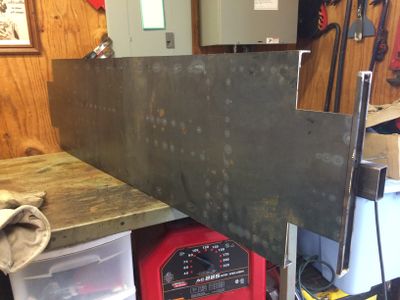
Top view of floor plate showing "kiss marks" from "stitch" welds underneath.
Bottom view of the floor shows stitch welds. These welds were made using a red Lincoln "tombstone" welder (seen under the table) with 1/8 inch 6011 rods. You must be very careful to prevent warping during welding, even with this thicker material. By careful I mean make short stitch welds (1/4 inch) and allow to cool between welds (10-15 seconds). Use lots of C-clamps to hold materials tightly together during welding.


Body
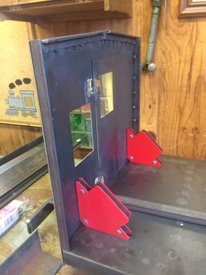
Angle iron has been stitched onto the end wall, which is now positioned for test fitting. I used small brass hinges for the doors, and brazed them to the steel. In retrospect I wish I had used rivets.
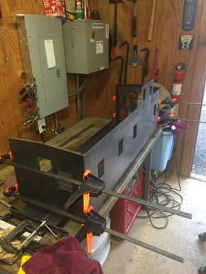
Preparing for welding the four sides together. The clamps are from Harbor Freight, and were made for wood projects, but I found they worked quite well for this project (and I already had them).
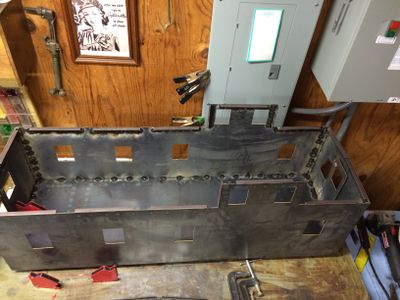
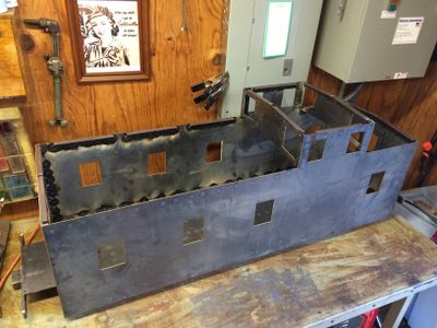
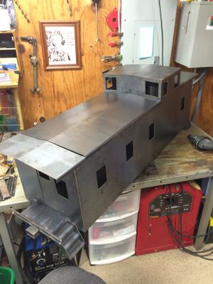
The four sides have been welded together and to the floor. Be sure to use a square to align the sides. Note the angle iron on the upper edge was welded in sections. This was a grave mistake on my part, as it causes severe warping of the sides. I later removed these and replaced with one long piece as the instructions suggest.
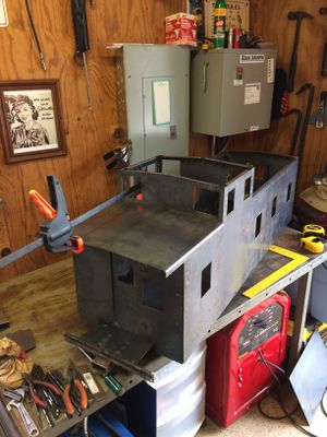
Angle iron has been welded to the edges of the cupola front and back sections.
The cupola front and back have been welded to the cupola sides.
The short section of the roof is prepared for welding. The roof is stitch welded on the inside.
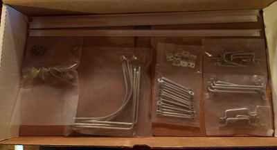
A box full of detail parts from Precision Steel Car.
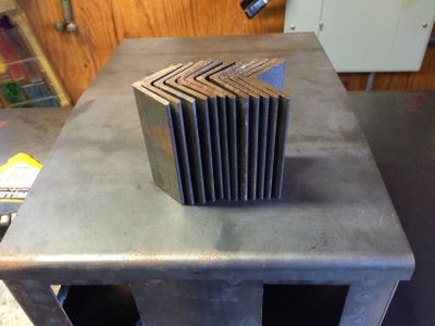
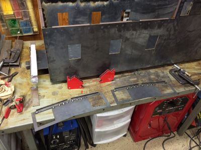
The steps must be cut the same length. I trimmed all these to the same length in the mill.
The instructions suggested clamping the steps to a section 1x1 inch angle aluminum. I chose instead to use magnetic holders, which worked quite well. In the background you can see where I blew a hole in the side of the caboose while welding. This was easily fixed later by filling in with a wire welder.
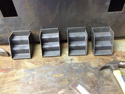
A complete set of welded steps.
A newly installed step.
View of the step from the underside, showing where the step is welded to the frame. Not very pretty, but it is strong and, luckily, will not be seen by the typical observer.
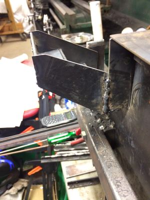
I chose to weld the step on two sides, namely, the side of the car and underneath the floor. It is not welded to the bumper.
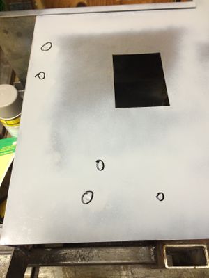
A coat of primer is sprayed on the side to identify dimples from welding that must be filled in. The dimples are circled.
Two of the dimples have been prepared for filling.
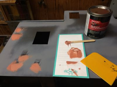
The dimples have been filled with "Bondo". Once set, the filled dimples will be sanded smooth.


Roof
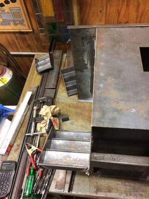
The Kitsap kit ships with three roof sections: a long section, the roof for the cupola, and the short section behind the cupola. I wanted a removable roof so that small children can ride in the caboose, so I took the advice given in the instructions to cut the long roof section into two parts as shown in this photo. This is where the Milwaukee metal cutting circular saw came in handy.
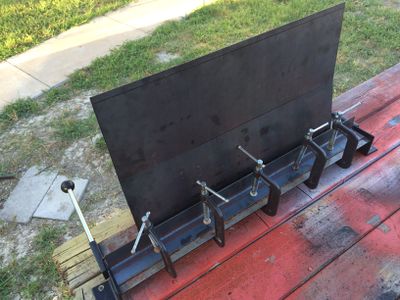
I used a low-cost sheet metal brake from Harbor Freight to bend all the roof sections. Here is the long roof section after cutting into two parts. This is the longest section and the hardest to bend in this jig. I used all the C-clamps I could round up. The bending operation worked smoother by spraying lubricant (WD-40) on the sheet metal where it was being bent.
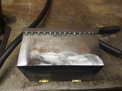
The short roof section cut from the long section has only about 3 inches of support to cling to. Three holes were drilled in the roof section on the left and right sides where it would sit on top of the roof beams. I first made stitch welds across the front of the caboose on the outside, underneath the roof section. You can see the "dots" of weld going up the photo. Then the six holes were fill welded with the wire welder, making sure the weld wire went all the way into the hole, attaching to the roof beam, and then filling the hole. The welds were ground flat with the roof. This resulted in a very strong roof section.


Battery Box
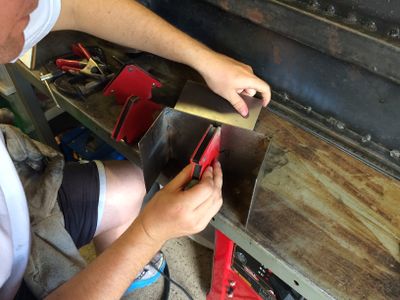
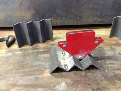
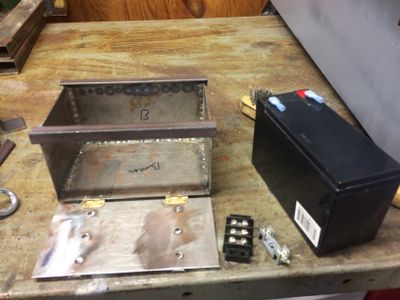
I decided to model the caboose after the Santa Fe caboose #999187 located at the Comanche & Indian Gap Railroad railroad. I needed a battery box in place of the tool cellar. Here my nephew Stephen is setting up to weld the box together. Note that this battery box was built from scratch, and is not part of the Kitsap Live Steamer's kit.
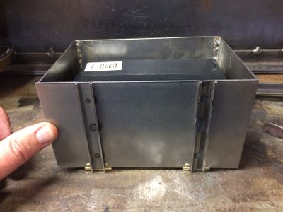
The dimensions of the box is 6-1/2 inches deep, 4-1/2 inches deep, and 3-3/4 inches high. After installation on the chassis the box looked a bit over-sized, so you may need to adjust for your taste. The battery box is large enough to hold a standard gel-cell battery. The battery will power the lights on the caboose. The two front braces were cut from 1/2 inch square steel tubing. It is cut down to about 1/8 inch high, so that the side ribs show prominently like the prototype.
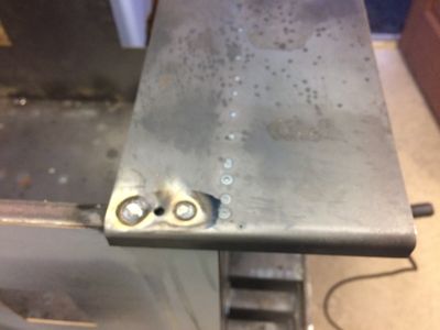
Here you can see the filler welds that hold the front braces onto the faceplate. Holes were drilled in the faceplate, the braces were clamped onto the faceplate, and the holes were filled with welds from the backside of the faceplate. The welds were ground down flat.
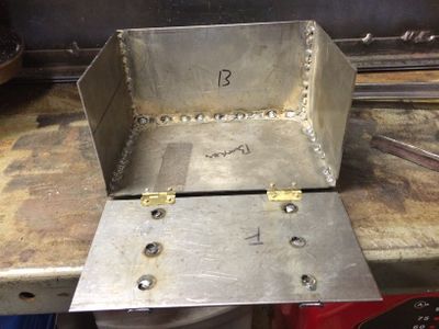
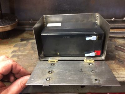
The box was welded together using "stitch" welds to prevent warping. Small brass hinges from Hobby Lobby are riveted to the box and faceplate using 3/32 inch aluminum rivets.
The top back mounting brace is welded onto the battery box.
The front brace is welded in place. Other components shown here include the terminal strip and the fuse holder.
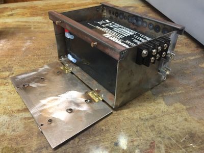
The terminal strip and fuse holder have been mounted on the side of the battery box. I made a mistake here, in that I mounted the terminal strip on the side where the air tank will reside. Not much access room after the battery box and air tank are mounted next to each other.
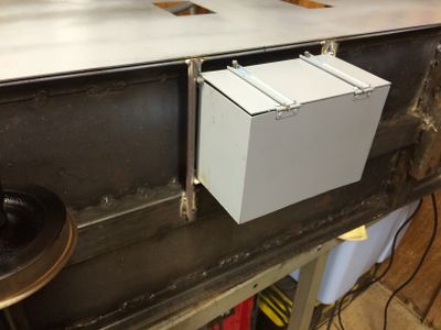
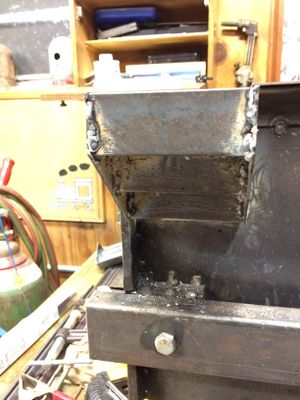
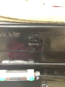
The battery box has been welded onto the caboose chassis. The mounting brackets are 1/2 by 1/2 inch angle steel. Two holes were drilled through the top of the two front braces through which #5-40 bolts are inserted, and screw into matching tapped holes in the front support brace.


Safety Chains
The instructions that came with the kit did not mention safety chains, so I had to decide where to attach the two chain hooks. I settled on welding a 1 inch by 1 inch steel angle on the center body beam, just behind the coupler attachment bolt. The eye bolts selected have long shanks, such that the eyes will be even with the end of the center beam. I later drilled holes for the eye shanks, but I wish I had drilled these holes before I welded the mount in place.
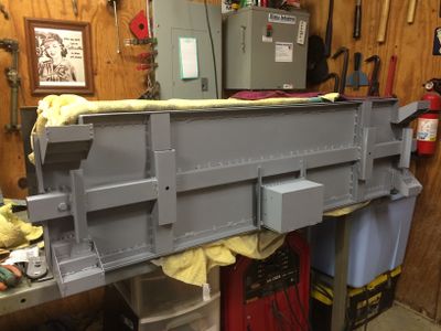
The underframe with primer paint.


Interior Paint
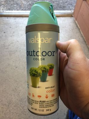
Valspar "Koi Pond Satin", part number 15310, is a close match to the light green color found in many prototype cabooses. (Take a look at the photos here.)
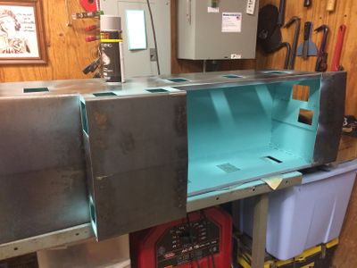
The caboose with a fresh coat of interior paint. This photo was taken with an iPhone in low light. The color is actually more green than the blue shown here.


Rounded Corners
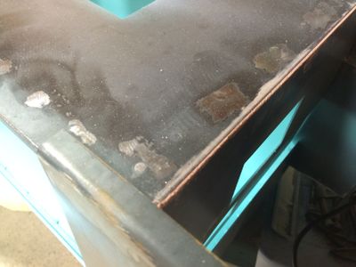
The corners of the caboose are to be rounded (but not the corners of the cupola). This is accomplished by first filling the corners with Bondo, as shown here.
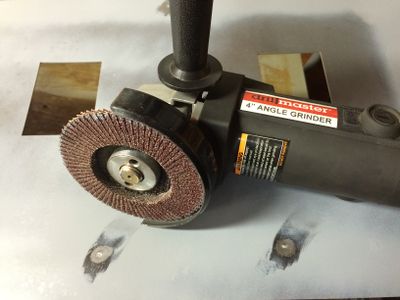
The corner is rounded by sanding. I used a grinder with an 60 grit sanding disk. Use gentle pressure and take your time.
Spray a light coat of primer on the corner to see imperfections that need to be sanded out.
Closeup of a finished corner.


Trucks and Brakes
See Balanced Air Brakes from Scratch.
Mounting Brackets
The air brake reservoir is supported by a section of 1/2 by 1/2 inch angle steel welded on edge on the center beam. You should provide more space between the battery box and the reservoir bracket than shown here.
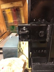
A mounting bracket for the release switch from 2 by 2 inch steel angle, and welded to the edge of the underframe.
Two brackets are fashioned from 2 by 2 inch angle steel and welded under each coupler pocket. These brackets hold the Clippard switches to the train line.
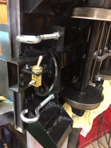
This view shows the Clippard TV-2S toggle valve installed in the mounting bracket. Note the eye hooks for safety chains, as required by some railroads.


Painting and Lettering
The free program Inkscape was used to create SVG files for all the vinyl lettering. The SVG files were then converted to EPS files used by the Vinyl Cutter. All graphics (SVG and EPS) are included in the following Zip file:
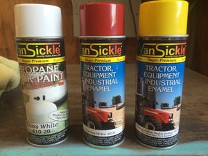
I found this VanSickle brand of enamel spray paint at a farm and ranch store named "Atwoods" in Greenville, Texas. Only the red and white was used on the caboose; yellow vinyl was used for the large "Santa Fe" logo instead.
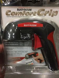
I highly recommend using a spray can pistol grip, such as this Rustoleum "Comfort Grip". This will help you make nice even coats of paint.
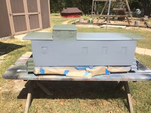
The car body was removed to an outdoor table where it was sprayed liberally with "Easy Off Oven Cleaner" to degrease the surface before painting. The degreaser was washed off thoroughly with water. Self-etching primer is then applied to the dry surface. The two different colors of primer resulted from running out of the gray and switching to a darker color.
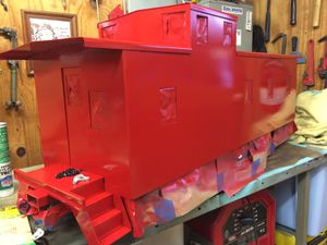
The body has been painted red and is ready for further detail work.
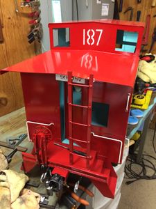
A vinyl negative was cut and used as a paint mask for the large "187" on this side of the cupola. I used positive while vinyl letters on the other side, and they both turned out well. Note the addition of details, such as hand rails, ladder and brake wheel.
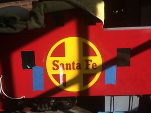
Two large 10 inch diameter "Santa Fe" logos were cut from yellow vinyl. Masking tape was applied adjacent to the location of the logo. Black marks were located on the tape by measuring from the bottom of the chassis. These marks were used as aids when applying the logo to keep it "level". The application tape has not yet been removed from the logo.
A 1/2 inch wide strip of yellow vinyl was applied after masking tape was placed at intervals to aid in alignment.
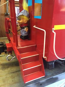
Narrow strips of white vinyl are applied to the top edge of each step for "safety".
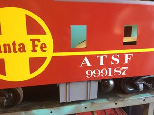
Road name and number applied on each side. If you haven't noticed already the caboose was numbered after the full size caboose at the Comanche & Indian Gap Railroad.
The road numbers are also placed on each end just above the door. These are white vinyl letters.


Brake Wheel
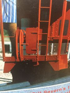
A closeup of the brake wheel of Harry Haas' steel caboose featured on the cover of Live Steam Magazine, November/December 1995. I used this basic design for the Kitsap caboose.
The brake wheel stand is cut from 1/4 by 1/4 inch angle steel. The bevels were cut on a mill.
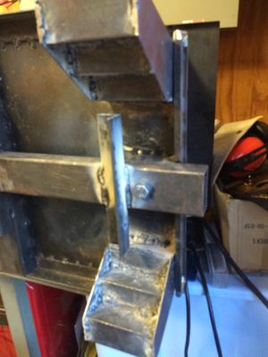
The back side of the brake wheel stand.
The front side of the brake stand.
The brake stand has been painted and installed. Four 5-40 by 3/4 inch bolts secure the brake stand to the bumper.


Hand Rails
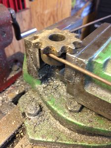
I wanted a nice wide-radius curve on the handrails. I found a small pully with a groove that was perfect for 1/8 inch diameter steel rod.
