1 inch Scale Freight Car Trucks
1 inch Scale Freight Car Truck
Colorado Central Design
by R.B. Bagley
Southern California Live Steamers
The Miniature Locomotive, July-August 1953
If you want a little project to help gain experience before tackling a locomotive, here is a good one. Flat cars and Gondolas are considered best for passenger hauling and since we've had a number of requests for an article on flat car building that will perhaps be the best place to start.
We'll concern ourselves with car trucks for this time, machining the aluminum car frame and other details to follow.
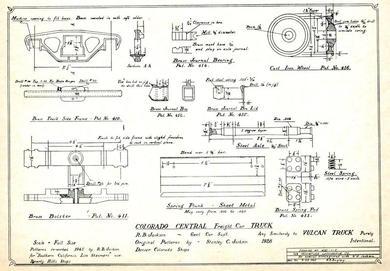
In 1945 R.B. Jackson altered the Colorado Central car patterns to leave only a minimum of metal to be removed during machining. This was for the special benefit of Southern California Live Steamers members that would have to do most of their work with a file. Hand filing is perhaps the most difficult of all shop work and few men accomplish the art, but this job doesn't require close tolerance.
We'll begin operations with the truck side frames. Simply clean off the flashing and other rough spots and file the opening in the center, for the bolster, to dimensions given on the drawing. Leave the openings at each end until after the journal boxes have been finished, then either mill or file so that the boxes will press in tight.
The journal boxes should first be trued up on the sides and back end with a file. Be careful to hold the 11/32 inch dimension from the frame fit to the back end of the box, lest you have trouble later on with wheels rubbing. File the front of the box to profile as shown on the drawing. The shape of the hinge is important because it controls the spring on the box lid, either to hold it closed or in the open position. An end mill is the best for cutting the hinge to 9/32 inch width. However, it can be done quite nicely with a file, being careful to scribe it first so that you can work to the line and keep the hinge centered.
Box lids only need cleaning with a file. Then drill the hole in the hinge for the pin. It is best to center punch and drill from both sides. If you plan to build more than one car it is advisable to make a jig for drilling the hinge. The box lids make a good jig to drill the hole in the part of the hinge on the journal boxes. Now comes the job of fitting springs to the box lids. This is the only tricky business in the whole works, but you will think it is well worth the trouble the first time you demonstrate to a friend how nicely they snap open or steel. I prefer spring bronze because it can be worked with the usual tools and saves making special punches and dies. It is difficult to describe exactly how the spring should be shaped and you will have to do a little experimenting on your own. The curve is approximately a figure "S" but rather open. The lower curve of the "S" fits snugly against the box lid where it is tightly riveted and the upper curve fits the under side of the hinge on the journal box. A 1/16 inch rivet is used to fasten the spring to the box lid and you can substitute a No. 0-80 screw and nut while experimenting. Some of the fellows have tried soldering the springs to the lids. This doesn't work and you may as well know that now. The heat ruins the spring. After the lids have been fitted to boxes and all holes drilled the boxes can be permanently pressed into the side frames and secured with soft solder.
Hold the bolster in a four jaw chuck on the lathe and take a facing cut across the two side bearings and also the center where it swivels on the car frame. Drill No. 12 right through the center boss for the bolster pin. The annular groove should be cut at this same setting. It may be done with a specially ground lathe tool (similar to a parting tool) and a depth stop should be used to maintain accuracy, or if you prefer, lock the lathe carriage and feed to depth by means of the dial on the compound. The notches in the ends of the bolster, where it fits the side frames, may either be milled or filed and should not fit too closely.
Spring pads need very little attention aside from the usual clean up with a file. The bottom pad is marked with two center holes. Drill them tapping size for either No. 5-40 or No. 6-32 as you prefer and use the pad for a jig to transfer the holes to the side frames. It may be well to mark each as you go, so that you will know where they fit. After all holes are drilled the spring pads may be tapped for screws.
The spring plank is made of light gauge metal to give it flexibility. This fits between the bottom spring pad and the side frame. The spring pad may also be used as a jig for drilling the holes in this piece. However, care should be used to maintain the 5-11/16 inch spacing between the two inside holes because the plank is used as a spreader to hold the side frames parallel.
Brasses are cast 8 in one stick. After the sides have been trued up by file or disc sander it is a simple matter to mill the half round bearing for the axle. Then cut them apart and finish each to length. This is one job that is almost as easy for the lads that don't have a mill, cut the bearings apart and clamp them in pairs in a drill vise, drill through and ream 3/8 inch. it is not advisable to try drilling more than two at a time as even the best of drills have a habit of going their own way (instead of yours) whenever they get the chance.
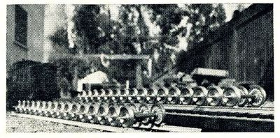
Wheels are next. We'll need a round nose lathe tool set for both diameter and facing cuts. A carriage stop is also in order. If you don't have one, a soft brass block and "C" clamp will do. Place one of the wheels in the three jaw, back side out. Set the carriage stop to allow for cutting the flange to diameter. If you are using the "C" clamp method, two spacing blocks will be needed for the facing cuts, lathe bits or small scraps of cold rolled will be OK. The first spacer should set the tool to face the back of the flange and a 3/16 inch spacer added will set it in place for the wheel hub face. It will be necessary to take several cuts before the carriage reaches the stop. In any event make the final cut light as this is the finish cut on the two faces. The flange diameter should be left 1/32 inch large to be finished later, when the wheels are pressed on the axles. Drill and ream the wheels at this same setting. Try the wheels in several positions in the three jaw until you have them running as true as possible. The reason for machining the back side of the wheels first is because of the cooling fins which are not to be machined and should be held concentric if possible. Once you have the set-up finish all 8 wheels on the back side.
Now you can reverse the wheels in the chuck and rough turn the front side and tire. Be sure to leave enough metal on the tire for a finish cut after the wheels have been pressed on the axles.
Screw machine stock is good for the axles, but cold rolled will do. Cut the axles to length, faced and center drill. Now if you want to cheat a little bit, here it is perfectly permissible, unless your three jaw is so far out of line that you can use it for turning eccentrics. Hold one end of the axle in the three jaw and work at the tail stock end using a center. Machine only to the center of the axle, then reverse ends and repeat the procedure. The rest needs no further explanation except to say that the wheels were purposely bored and reamed before making the axles. That gave us a chance to check the holes in case the reamer had cut over size and it is much easier to make the axles slightly larger for the press fit than to shrink the holes in the wheels to make them fit the axles.
Use white lead when you press the wheels on the axles so that it will be possible to remove them someday should that be necessary.
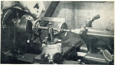
After the wheels are pressed on the axles you can finish turning the treads and flanges by the same method as described for the axles. The set-up is shown in the photo. When shaping the flanges, slight alteration can be made to correct spacing if needed.
The truck is now ready to assemble. Assuming that journal boxes and lids have already become part of the side frames, place a brass on the end of one axle and slip them into the journal box from the back side. If all goes well try again with the other axle and then repeat for the other side. The bolster will slide in through the large opening in the side frame. Then shove the spring plank in position. The spring pads, with springs in place, are pushed between the bolster and spring plank. When all is in place turn the truck bottom side up and line for the four screws that hold the works together.
When the truck is completely assembled there should be a minimum of 1/16 inch clearance between top side of bolster and the opening in the side frames. This is an important detail if you wish to avoid derailments.


