Van Brocklin Mechanical Lubricator
Mechanical Lubricator
The North American Live Steamer, Volume 1 Number 5, 1956
This type of lubricator has been used on three different engines within the last seven years and has been practically fool-proof in operation during that time. It has several advantages, mostly in being simple to make and very little alignment problems to worry about. It can be driven in either direction and requires little power. This one described is a twin cylinder job, 3/32 inch bore by 3/16 inch stroke as used on my 3-1/2 inch gauge Atlantic "Juniper". Each cylinder (1-1/4 inch by 1-3/4 inch) of the engine has separate feed to insure a constant supply of oil to the 3/4 inch diameter piston valves and pistons. However, it can be made as a single cylinder unit for those who like.
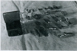
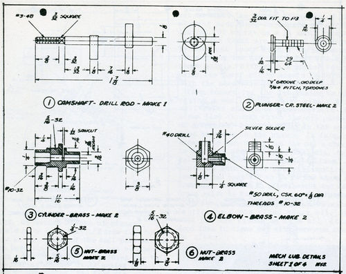
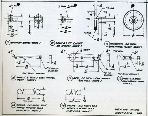
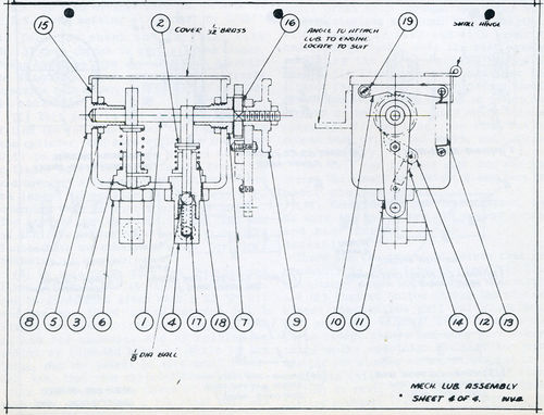
The drawings speak for themselves pretty well, I believe, but a few tips on making the various parts and assembly might be in order. I'll just mention the points that need some words of explanation, going by part numbers of drawings.
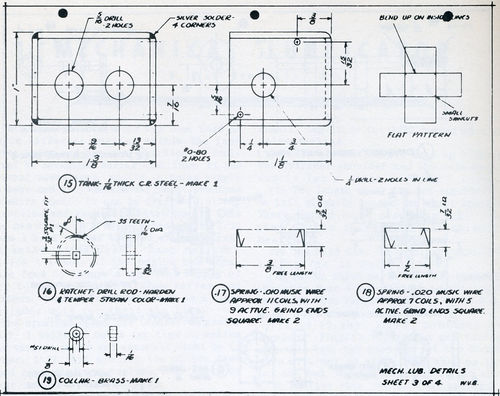
(1) The cams of this part can be made of CRS rod, setting off center by 3/32 inch in four jaw chuck and drilling with No. 31 deep enough to part off two blanks. Press each one from opposite ends of shaft to dimensions shown and with eccentricity opposite each other. Silver solder in place if necessary.
(2) This part is the only really close fit on the job. The better the plunger fits the cylinder, the more efficient your pump will be. This should be fitted to each cylinder so it will just slide freely up and down, yet without any side shake. It can be lapped to cylinder with a very fine compound such as rotten stone or pumice. The grooves are in added luxury, though not an absolute necessity. The length is 1/64 inch longer than necessary to allow for final trimming at assembly.
(3) On this part, turn the threaded end first and drill No. 46 right through. Open out to dimensions given with 5/32 inch D bit and tap No. 10-32 being careful not to strike the flat bottom hole. Cut off and finish the opposite end by holding in collet or threaded bushing. While in the lathe, put the saw-cut in with small jewelers' saw, then ream cylinder bore 3/32 inch diameter.
This will remove any burrs or distortions caused by saw-cut. Use a 1/8 inch steel ball and lightly tap it on the 3/32 inch reamed hole for valve seating.
(4) The threads should make up tight to the cylinder shoulder and the countersunk end is for a union on 3/32 inch tubing.
(7) The length under the hex shoulder can be left slightly longer for shaft spacing. There should be no more than 1/64 inch end play of the shaft when assembled in bearings.
(9) The 3/16 inch diameter on this part should be a free fit in hole of arm.
(10,12) On these parts the case-hardening should be done after fitting to ratchet at assembly. When ratchet gear all works O.K., then harden up. Ed. See Machining Lubricator Ratchet Wheels.
(13, 14, 17, 18) You'll probably get "springy" fingers before you get through with this job, but once you get the correct size of arbor to wind, from then on it's not too bad. Roughly, the arbors are about 1/32 inch smaller than the I. D. of springs. A small cross hole through the arbor will help in starting the winding. Hold a length of wire tightly in hand and with arbor in headstock of lathe, pull the belt slowly, advancing the wire. Springs 17 and 18 should fit freely in hole and over the plunger respectively. These springs should not be too stiff. Just enough to return the plunger or ball. Here again check this at assembly. If too long, the ends can be ground back or, if too short, pull spring apart evenly.
(15) This can be made most any way you desire. The length and height dimensions are about minimum size.
(16) These wheels can be purchased, but be sure the teeth are all spread evenly and same depth.
Assembly
There are two important points that are necessary in this type of pump. (1) That the plunger opens port fully at top stroke and (2) That at bottom stroke the plunger almost touches the ball valve. We don't want any "lost volumes" here. Assemble all parts except elbows and make sure everything works smoothly. To list for port opening put plunger on top stroke and try a 1/32 inch shim (with a short end bent at right angles) in port. It should slip in without hitting plunger. Trim end of plunger if too long. On bottom stroke of plunger, it should be no more than 1/32 inch from flat bottom hole as the radius of the ball extends into the bore about 0.020 inches. This can be checked with a depth gauge or by holding the ball and feeling whether it is seated firmly or not. If not seated, the 5/16 inch diameter shoulder on the cylinder can be skimmed off to drop cylinder deeper in tank. If clearance too great, deepen flat bottom hole.
Another point which you will probably notice by now is that on top stroke the plunger hits the bushing. This is as it should be. The cam should clear the end of the plunger slightly at this point to allow the ratchet to move a few teeth, not moving the plunger. This allows a time delay while the port is open for the heavy oil to completely fill the cylinder. To get this-file a little from the narrow edge of the cam.
When finished, the lubricator can be tried by hand with light oil in the tank and pumping up against a pressure gauge. It whould go up to 200 pounds without any trouble and hold that pressure if your fittings are tight and good seats in the ball valves.
The amount of oil an engine will consume depends on many things, cylinder diameter wheels, whether superheated or not and so on.
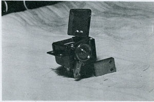
To get some kind of adjustment on the ratchet wheel movement, I made an arrangement as shown in the photo. It essentially consists of a plain eccentric disc on the leading axle with a spring loaded plunger and stop collar. The collar being set to limit the amount of return of the plunger according to the length of the stroke desired. Of course on a 35 tooth ratchet one or two teeth are all that is needed. To move one tooth with a 15/16 inch center distance on the arm, the stroke would be about 3/16 inch. With such a spring return drive, the power stroke should be forward with the eccentric pushing.
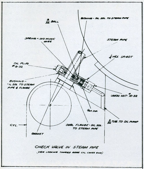
When connecting the lubricator to the engine a small check valve with a 3/32 inch ball valve should be somewhere in the steam line through which the oil passes. On my engine, I put it right in the steam pipe as shown in the photos. It is quite accessible here and gives the oil a chance to mix with steam. I need 3/32 inch diameter thin wall brass tubing for the feed lines. In photo of lubricator you will notice a bushing and bent rod which is not shown on drawings. This was an afterthought and is a drain valve in the tank for cleanout purposes.
To function properly, any mechanical lubricator needs clean heavy oil. Dirt will put the kibosh on them all. It's a good idea to clean out with kerosene every so often.
See also Turning Eccentrics in Three-Jaw Chuck.
