Turbine Generator: Difference between revisions
| Line 7: | Line 7: | ||
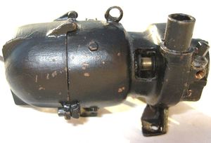
File:Moseley Generator MO-6 PyleNational 02.JPG | File:Moseley Generator MO-6 PyleNational 02.JPG | ||
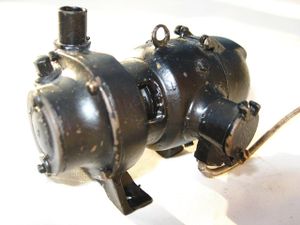
File:Moseley Generator MO-6 PyleNational 03.JPG | File:Moseley Generator MO-6 PyleNational 03.JPG | ||
File:MosleyGeneratorTurbine2017.jpg|Moseley Generator showing the internal turbine blades. Photo by Karl Kobel. | |||
</gallery> | </gallery> | ||
Revision as of 20:41, 24 April 2017
1 inch scale
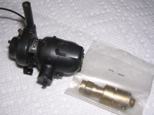
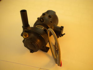
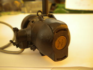
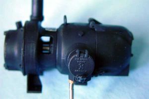
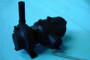
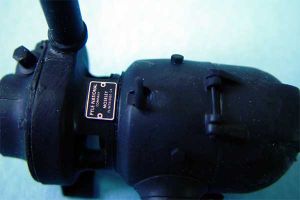
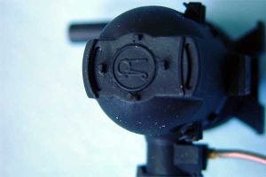
Moseley 1-inch scale turbo generator

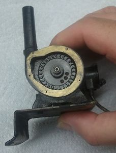
Moseley Generator showing the internal turbine blades. Photo by Karl Kobel.


1.5 inch scale
Turbo Generator(1.5 inch scale) by Francis Moseley.
Moseley 1.5 inch Turbine Generator manufactured by Riding Railkits Inc


Design Principles
There are lots of ways to find an end to a problem, but don't overlook K.I.S.S. ! Think about the entire system and how it works, what is available for input and most of all, what you want out of it. I have built enough miniature "dynamos" to find that simple is as simple does.
- 1.5" scale units must have small turbine wheels and the resulting need for high speeds.
- A rotor built with speed in mind has no problem with 100K + RPM should it occur.
- Steam issuing from a nozzle has a limited velocity and the blades will likely not attain 50% of that especially when driving a load. Always keep a load ON.
- Control the steam feed with small pipe. 1/8" copper tube is plenty. Flow is controlled by the nozzle aperture. For best velocity use a venturi. Convergent-divergent tapers.
- Don't forget the boiler operating range. Still having lights at 60 psi would be nice. So, having a wide range of output voltage followed by an electronic regulator is similar to the locomotive boiler. Reserve pressure is useful when needed.
- Spinning magnets in a wound field makes an alternator (think automotive). Full wave rectify the output in the unit and ground the minus lead. Now one hot lead is all you need. Less mess. The loco chassis is ground (circuit return). Use Teflon #20 lamp leads.
- A simple 3 terminal regulator chip (LM317 from Radio Shack) is adjustable and self limiting for over temp and current. It shuts down in case of a fault. Use as many as needed for different circuits/lamps. See the spec sheet for limitations (operating area).
- Use low voltage lamps (large selection of 3V types - or LEDs) to avoid the need for large numbers of turns in the field thus allowing large dia wire to keep the internal resistance as low as possible. Resistance eats amps. #22 or 20 works well.
- The schematic attached is as simple as it gets. Don't forget a heat sink.
- The dyno can attain nearly 400° F in operation sitting on top of a boiler. Internal electronics have to be pretty tough to servive and work as well. Ventilation is a must.
By the way, the MO-6 Pyle National Dyno has 3 speed control systems built in. Centrifugal governor steam valve, over-speed brake and an eddy current drag disc for over-current. Can't fit all that in a miniature. Shaft rotates CCW. 3450 RPM. 32V. There are also 4 nozzles. Two primary and two secondary.
RichD toolman8(at)copper(dot)net

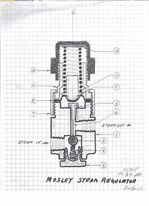
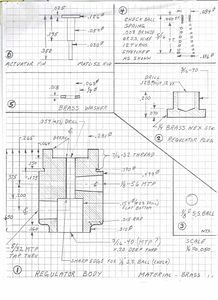
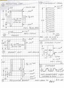
Pressure Regulator
Rich Carlstedt provided drawings for the Moseley pressure regulator:
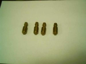
Original Mosley turbo generator regulators. Photo by David Sclavi


References
External Links
- Photo of turbo generator for a Big Boy
- Moseley Generator Regulator
- "Steam Turbo Generator", Richard Chiapparelli, Live Steam Magazine, Part 1 September-October 1998, Part 2 November-December 1998
- "1.5" scale Live steam Mosley generator 1:8 scale", Shapeways
- "LS Mfg MO-6 Turbogenerator Castings", Chaski.org
- List of articles on Turbine Generators, Chaski.org
- "For Those of You Into Working Turbogenerators", Chaski.org
- "Moseley Generator", Chaski.org
- "Pyle National Turbo generator MO-6", Chaski.org
- "Steam turbine generator", Chaski.org