Stability Of 7 1/2 Inch Gauge Ride-On Trains: Difference between revisions
(Created page with "Category:Safety by Bill Donovan, <i>Real Trains Inc</i> == Introduction == Large scale trains operating on 7 1/2” (or 7 1/4” in some areas) gauge track have ope...") |
|||
| Line 34: | Line 34: | ||
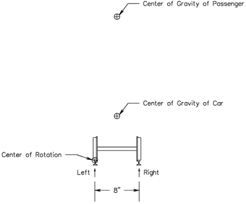
This reduces our stability analysis to what is shown in Figure 1. While the track gauge is 7 1/2”, the actual point of contact between the wheels and rails is somewhat wider. We have simplified our analysis by assuming this distance is 8”. | This reduces our stability analysis to what is shown in Figure 1. While the track gauge is 7 1/2”, the actual point of contact between the wheels and rails is somewhat wider. We have simplified our analysis by assuming this distance is 8”. | ||
[[File:Stability of riding cards figure 1.png|thumb|center| | [[File:Stability of riding cards figure 1.png|thumb|center|500px|Figure 1 - Basis of Analysis]] | ||
We can define stability as positive, neutral, and negative. We have selected the point of contact between the left side wheel and left rail as a point about which all of our calculations will pivot. This means that positive stability is when there is some amount of downward force on the right side wheel to rail contact. While actual operation will require this to be at least a moderate amount for this analysis we will assume positive stability with any amount of force here at all. | We can define stability as positive, neutral, and negative. We have selected the point of contact between the left side wheel and left rail as a point about which all of our calculations will pivot. This means that positive stability is when there is some amount of downward force on the right side wheel to rail contact. While actual operation will require this to be at least a moderate amount for this analysis we will assume positive stability with any amount of force here at all. | ||
Revision as of 22:26, 17 September 2013
by Bill Donovan, Real Trains Inc
Introduction
Large scale trains operating on 7 1/2” (or 7 1/4” in some areas) gauge track have operated safely for many thousands of miles carrying passengers of all types. They have an amazing ability to accommodate persons of varying ages, many sizes, and those with disabilities. We are all familiar with clubs that offer rides to persons beyond the immediate friends and family of the club member or equipment owner. The public service record of providing a fun, safe day to scout troops, cancer survivors, and birthday parties is one of he outstanding merits of being involved in the operation of these trains.
History
For many years small amusement ride operations used train equipment approximately one-quarter full size, most commonly on 15 inch gauge track. This size of equipment was very stable and dependable for commercial operations. It required a great deal of space for track and storage, was heavy to transport if moved, and was unaffordable to many individual hobbyists.
With time a new size based on dividing 15 inch gauge in half resulted in the 7 1/2” gauge equipment that is so common today. This also made possible larger size, more complex, and more detailed models as individual preferences developed. The smaller scale made possible home layouts, and models that could be taken from home to home or to clubs.
Ridership
In years past the common approach to a club or private track offering rides was that it was understood that the builder, owner, and operator were all amateurs. They did not do any of these things for a living, were not an expert, and were offering to do the best they could in providing a safe experience in riding a model train.
In the past few years some operators seem to have moved away from this view. Perhaps it is the desire to appear professional in what we do. For some clubs that are on public land it is a pressure from outside to provide more rides with less restrictions on who can ride. In a few cases it was motivated by an ability to collect money, either as a fare or as a donation, for providing the rides.
We really don’t like to say it but we are more and more living in a society in which any problem ends up in the legal system. If you are offering rides to persons that feel they are being transported by a system equivalent to a commercial amusement park, they are more likely to demand significant attention if anything goes wrong.
The combined pressures of carrying persons who, in the past, may not have been allowed to ride, and the likelihood of serious legal, insurance, and financial issues if there is an accident, combine to make many persons reluctant to participate. However, if this is carried to extreme the clubs and tracks we all need to enjoy our equipment will disappear. It is admittedly a pleasure to operate your locomotive with a good load to pull. And hopefully the pleasure provided to the passengers will also bring you joy. So we need to look carefully at the equipment we operate and understand the limitations in what it can and cannot do for us.
Background and Terminology
This document focuses on equipment operating on 7 1/2” gauge track. In the case of 7 1/4” gauge the results would be very similar and the work done here has not been repeated for this other size. The information presented applies to any scale (1 1/2, 1.6, 2 1/2, etc.) that operates on this gauge track. For smaller scales and narrower gauges it is certain that most persons operating this equipment understand that they are very limited in who they can allow to ride because of the lesser stability. In looking at larger gauges, 9” is somewhat more stable than the results shown here. Still larger gauges, 12” and above, benefit greatly from the combination of wider wheel spacing and much heavier cars. Once we get to 15” gauge we are in the range of commercial operations that can safely operate with a wide range of passenger types.
Defining Stability
In looking at how to transport a passenger safely we must consider three components, the passenger, the car, and the track. This assumes that the car includes any seating, supports, footrests, etc. as a rigid part of the car. For passengers we will simplify all the possible shapes and sizes to simply consider their weight (mass) concentrated a single point.
This reduces our stability analysis to what is shown in Figure 1. While the track gauge is 7 1/2”, the actual point of contact between the wheels and rails is somewhat wider. We have simplified our analysis by assuming this distance is 8”.
We can define stability as positive, neutral, and negative. We have selected the point of contact between the left side wheel and left rail as a point about which all of our calculations will pivot. This means that positive stability is when there is some amount of downward force on the right side wheel to rail contact. While actual operation will require this to be at least a moderate amount for this analysis we will assume positive stability with any amount of force here at all.
Neutral stability is then when the force between the right side wheel and rail is zero. This is a single value that we will use in our analysis to divide acceptable positive stability from unacceptable negative stability.
Negative stability is then when there is an upward force at the right wheel. This will result in our entire system of passengers and car rotating counterclockwise around the pivot point until stopped by some other limitation (such as the frame hitting the ground). This is the stability result we want to avoid.
Moments and Forces
The analysis used for most of this report is based on the engineering science of statics. In this we are considering forces that are unchanging (static) during the analysis. In a complete analysis we would consider linear forces (up and down) and rotational (turning) forces. For our analysis here we need only consider these rotational forces as a torque. The unit of torque we will use is the inch-pound which is defined as a force of one pound operating on a moment arm of one inch. In all cases we are simply using a weight in pounds as the force.
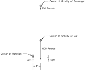
Since the left side wheel to rail contact point is our pivot point we will analyze rotary moments about this point. In order to show the difficulty of obtaining stability we have decided to use weights that in many cases are much larger than typically found in this size of equipment. In all of the following analysis we will use a weight of 1000 pounds for an empty car. We will then also use a weight of 200 pounds for the passenger that is the focus of this analysis, that is, someone that causes a stability problem.
We can now redraw the initial figure in a more typical engineering way as shown in Figure 2. We show the weights as downward pointing arrows and we have made the length of the arrows proportional to the amount of weight.
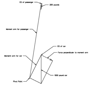
In a conventional analysis this figure, plus the horizontal and vertical dimensions to each of the forces would be analyzed as shown in Figure 3. It is necessary to calculate the length of each moment arm along its diagonal. It is also necessary to break the force from the weight into its component part that is perpendicular to the moment arm. This analysis requires considerable math and yields the same result of a simplified method discussed in the next section.
Analysis in One Dimension
To simplify our analysis we can eliminate the vertical information and consider only the forces and their horizontal positioning as shown in Figure 4. If we were doing a complete analysis and wanted to know the vertical and horizontal forces at every point, including the pivot point, we could not make this simplification.


