Some Notes on Springs
The Modelmaker, Volume 7, Number 4, April 1930
How many times has the question been asked by the amateur model maker "what size material shall I use" or how man springs have been made of different sizes of material, different number of coil springs, or different thickness, width and number of leaves in leaf springs in an endeavor to obtain one that will suit a given set of conditions?
If we analyze the factors that make up spring design, we will find the following interrelated main groups. Those factors that may be classed as "physical" and a second group that may be classed as "dynamic." Under the former heading we would have the dimensions of the spring as a whole as well as its parts, while the latter would embrace the loads and the deflections or movement under any particular load.
We will now have to consider particular types of springs, and while there are quite a variety made to meet particular conditions the amateur model maker will probably only need "leaf springs" of the type known as "semi" or "full elliptic" and "spiral springs" of round wire.
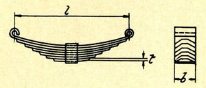
Taking a leaf spring (Figure 1) we will note that it consists of a number of leaves of certain thickness and width also that the longest leaf is a definite distance from eye to eye or span and the others are evenly reduced or graduated in length. If we support the spring by its eyes and place a "load" on its center it will be seen to deflect and in doing so will "stress" the material of which the spring is made. "Stress" is a definite load per unit of area, usually one square inch, and this term must not be used when "load" is meant.
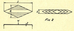
Now we have seven factors to deal with and perhaps it may be seen why a mere hit and miss method of spring making is likely to benefit no one but the metal merchant. All seven factors must harmonize to produce any desired spring and this harmony can be expressed as an equation. Before doing this however, let us consider a single plate or leaf cut diamond shape, Figure 2, supported at ends and loaded at center with load (W). The equation that harmonizes the load factors above mentioned is given by
where
- W = Maximum safe load in pounds
- S = Safe stress in pounds per square inch
- t = Thickness of plate in inches
- L = Span in inches
Now the stress in such a plate will be uniform throughout its length and if we clip off a narrow strip each side and keep on till the middle strip is reached and then pile all the pairs of strips on one another, we will obtain a theoretical ideal spring. In other words instead of having a wide one leaf spring, we will have a multiple narrow leaf spring of exactly the same characteristics as far as load capacity and deflection is concerned. It will now be apparent why springs of this type have leaves of evenly decreasing length and also why the ends should be either pointed or tapered. It will also be seen that an ideal spring would have a very short bottom leaf. Practical considerations will, of course, modify, for we must have a buckle and also the ends of top leaf must be square to take hangers or eyes, but the nearer to the ideal form the spring is made the better.
We can now write our equation:
because instead of using one leaf of width B we will use a number of leaves (n) each of width (b). Expressed in terms this merely means that: the load W is numerically equal to twice the stress multiplied by the number of leaves, the width of leaves and the thickness squared (i.e. the thickness multiplied by itself) and divided by three times the span.
For spring steel the stress is usually taken by 80,000 lbs. per sq. in. and by placing this in our equation and eliminating the numerals we obtain
This is the usual form and may be taken for any size semi-elliptic spring whether model or full size. If definite values are placed in and the equation worked out the amateur will very readily discovered why an actual spring, say a locomotive spring when exactly reduced to scale would be far too stiff for the model.
Now a clear idea of relative proportioning can be obtained by merely examining this formula. Thus we can say that the Capacity or Maximum safe load is:
- (a) Directly proportional to the number of leaves
- (b) Directly proportional to the width of leaves
- (c) Directly proportional to the square thickness of leaf
- (d) Indirectly proportional to span
Thus we may increase the capacity of any given spring by increasing the number of leaves, their width or both, or by decreasing the span, the capacity increasing in exact proportion with the changes, but if we increase the thickness of leaves the capacity will be much more rapidly augmented, doubling the thickness would raise the capacity four times.
Before we are in a position to design any particular spring we have to consider the relation between the load and the deflection; as in the above equation we have only considered the capacity or maximum safe load in relation to the resistance or strength of the material.
The deflection for the load W is given by
where (d) equals the deflection in inches and (L) and (t) as before.
Now note that the deflection is directly proportional to the square of the span and indirectly proportional to the thickness of leaf, also note that the width and number of leaves do not influence the deflection, (L) and (t), being constant. that is to say the addition of leaves to a spring will increase the carrying capacity but the deflection under this increased load will be precisely the same as that under the capacity load before the alteration.
To illustrate use of above considerations, suppose we need a leaf spring of 2 inch span, to carry 10 pounds maximum load and constructional requirements limit the width of leaves to 1/4 inch, and the deflection under this is to be 3/8 inch.
First find the thickness of leaf material from deflection formula
or
Putting in the known values, we get
Now taking the capacity formula
and putting in the known values.
or
To sum up above statements, if a stiff strong spring is desired use a small number of thick leaves. If a strong flexible spring is desired use a large number of thin leaves. Having found the number and thickness of leaves, it is an easy matter to so modify either or both to meet available thickness of commercial material and rework the deflection and capacity. Here is where the discussion on the relation of load deflection, width, number and thickness of leaves comes useful.
If we connect two leaf springs together upon one another, that is a "full elliptic", the capacity will be exactly the same as for the semi elliptic but the deflection will be doubled.
The maximum capacity of a spring is usually taken as meaning that load which would bring a leaf spring flat or a spiral spring solid and the working load is taken as sixty per cent of this.
If the above notes are followed, no difficulty will be experienced in dealing with the fundamentals of spiral spring design.
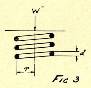
The formula which gives us the capacity for springs of round wire is:
where
- W = Capacity or load to close solid in pounds
- r = Means radius of coil in inches
- d = Diameter of wire in inches
Expressed in terms we would say that the Capacity varies directly as the cube of the diameter of the wire and inversely as the radius of coil.
Now note that the number of coils do not enter into the equation at all, so that the capacity of one coil of any particular spring is exactly the same as a number of coils. In other words, it would take the same load to close solid in twenty coil spring as to flatten down only one coil of it. This is exactly opposite to the leaf spring where the capacity bears a direct proportion to the number of leaves. The formula will also show that due to the fact that the diameter of wire is cubed (d*d*d) the capacity rapidly increases with even small increments of wire diameter. THus if we double the diameter of the wire of a definite radius coil, we shall obtain (2*2*2) eight times the capacity where as by doubling the diameter or radius of coil, we shall have the capacity.
The deflection is given by:
where
- D = Deflection in inches
- n = Number of coils
- r and d being as before
In this formula it will immediately be seen that the greater the number of coils, the greater the deflection under the capacity load and also the deflection would rapidly increase with increments of mean radius, and would decrease the increments of wire diameter.
Now let us take an example.
A round wire coil spring is required to give a capacity of 10 pounds with a mean radius of coil of 1/4 inch and a total deflection of 1/2 inch. Find diameter of wire and number of coils.
Taking the capacity formula we can find the diameter of wire. Thus:
- d = 0.054 inches
The number of coils required to give the deflection called for is given by formula.
We now have the principal dimensions of the spring from which it is an easy matter to find the height of the spring both when closed solid and free.
Thus:
- Solid height = number of coils * diameter of wire
- free height = solid height plus deflection = 0.22 + 0.05 = 0.72 inches
So that if it is desired to make such a spring we would have to wind up 5 coils over a distance of 0.72 inches or each coil would have a pitche of
For practical purposes, these figures would perhaps have to be modified. These points will be discussed later. But if the above principles are grasped, very much work will be saved in eliminating trial and error methods.


