Small Pressure Gauges
by H.L. Swan
The Model Craftsman, March 1937
The appearance of many an otherwise true to scale model is often marred by a pressure gauge which scales two or three feet in diameter and a foot or over in thickness.
The difficulty lies in the fact that a reliable gauge is essential and that model makers have found by experience that it is difficult to make, or obtain at a reasonable price, an accurate instrument of the small size permissible which will measure the relatively high pressures commonly used in model boilers.
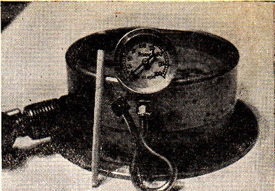
The pressure gauge shown by the photographs and drawings is the result of a number of experiments made with the object of determining the most suitable type and simplest form of construction with which satisfactory results could be obtained.
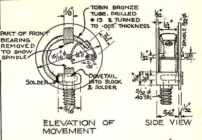
The Bourdon or bent tube is the essential working part. To make this take a piece of 1/4 inch diameter Tobin bronze welding rod 2 inches in length, chuck it in a universal chuck and drill it axially with a #13 drill. Grind the drill carefully to get both cutting edges exactly the same length and angle as a straight hole is absolutely necessary.
Mount the drilled rod on a mandrel between centres and turn down to an outside diameter 0.010 inch larger than the mandrel, finishing carefully with a square edge tool as the finished tube will only be 0.005 inches thick and tool grooves would be certain to cause the tube to split during the bending process. The next step is to bend the tube and the best way of doing this is to fill it with solder and work it carefully around a 5/8 inch diameter rod with a very light hammer, but before doing this anneal it thoroughly and flatten it slightly. Thin bronze is very easily overheated and care is necessary in the annealing. When bending, wrinkles are bound to appear on the inside. Keep these from working to points or the metal will tear. The exact curve of the tube is unimportant so long as it can be fitted into the block at the base and can be given room for the slight movement it makes inside the case. Do not use rosin core solder for filling the tube as it will leave pockets which will collapse when bending.
The block mounting is made next from a piece of 3/8 inch brass rod. Turn the thread the rail pipe connection and make the oval hole for the tube by drilling a hole in the rod with a #10 drill at right angles to the tail pipe connection, annealing the rod and flattening it in the vise to the required shape. Care must be taken to protect the connection while this is being done by running a long nut or threaded block down over the threads. Fit the bent tube snugly into the block and soft solder in place. The plug for the dead end of the tube is filed from 1/16 inch sheet brass and soldered in place.
At this stage it is advisable to connect the mounted tube to the city water supply and check for leaks. With the ordinary city pressure of from 75 to 100 pounds there should be a perceptible straightening of the tube.
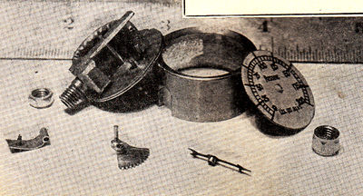
The quadrant is best made from a spokeless watch wheel cut down to about twelve teeth. The pinion is cut in the spindle by using the lathe as a shaper. Mount a narrow parting tool sideways, clamp the headstock with the back gear, take a light cut with longitudinal feed, release the headstock, turn one sixth of a revolution and so on until the teeth are deep enough to mesh with the quadrant.
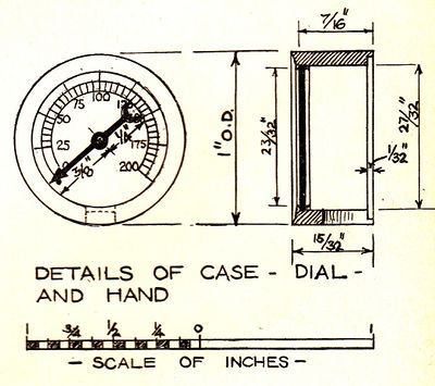
The connecting link is made from sheet brass and secured with a screw out of the old watch. If you have no tap this size file one of the screws square and if carefully started it will cut a good thread. The hand is filed to shape from a scrap of watch spring, and tempered in oil to restore the blueing.
The dial is made from a disc cut out of a cigarette tin already enameled white and graduated with drawing ink. Mica is used for the glass secured with a spring ring of brass.
The gauge should be calibrated with a standard gauge and marked in pencil at four or five points. The intermediate readings may be interpolated. Always use a siphon or "U" tube on the steam supply.


