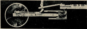
Mock-Up Valve Gear
Mock-up Valve Gear
A Trick That Really Pays Off
by Jack M. Fesco
The Miniature Locomotive, November-December 1953
If you want to check your Walschaert Valve gear by observing the valve events, pre-admission, but off, release and closure, before actually building the one to go on your engine, this can be accomplished by making up a mock-up valve gear which is a model itself. The parts can be made from scrap usually found around the shop.
In this case the scale is 3/4 inch. Drivers 5 inch diameter, cylinders 1-2/8 inch bore by 1-3/4 inch stroke. Valve travel 17/32 inch, steam port 5/23 inch, lap 3/32 inch, lead 1/64 inch, exhaust line in line, link radius 4 inch, back set of link foot 29/64 inch.
The crank pin is placed 7/8 inch from wheel center.
The eccentric crank is made adjustable and can be tightened down by 2 set screws. The eccentric crank pin is 1-1/8 inch from main pin. The eccentric rod, union link, and valve stem, are threaded on both ends for adjustment.
The link has no slot, 1/8 inch pins are used instead, spaced 5/8 inch from trunion pion.
The valve chamber bushing is reamed 1/4 inch and the steam admission and exhaust ports are milled in.
Next we make a 1/4 inch diameter valve bobbin and screw it into the valve stem crosshead.
A 1/16 inch thick dural sheet 7 inch wide 18 inch long is mounted on 3/8 inch plywood. The cylinder, valve chamber and link center lines are layed out and scribed respectively, and the valve motion parts are fastended onto the sheet.
First we must find the forward and back dead centers on the wheel by scribing on the wheel with a tram dividers and center punched.
Now after all of the parts are assembled, radius rod placed on lower link pin, the wheel is revolved forward until top quarter is reached. The eccentric crank is set approximately on back dead center and tightened with set screws.
Now we will continue the rotation of the wheel forward until its forward dead portion is reached, and by observing the movement of the valve through the bushing the front steam port should open the amount of lead 1/64 inch.
Advancing or retarding the eccentric crank or adjusting the eccentric rod will give the correct lead. The same result can be obtained on back dead center.
Note on either the forward or back dead center the link assumed a vertical center position.
Now, by changing the position of the radius rod to the upper link pin an equal motion is imparted to the valve by revolving the wheel backward, and the eight valve events can be scribed on the wheel for one complete revolution.
By placing the radius rod on link center trunion pin the only motion that is imparted to the valve is through the crosshead, union link, and combination lever which is twice the lead plus twice the lap.
The time spent in making such a model will more than compensate for itself, as it eliminates a lot of headaches and guess work and enables you to transfer the measurements to the real parts, for the Live Steam Loco under construction.
