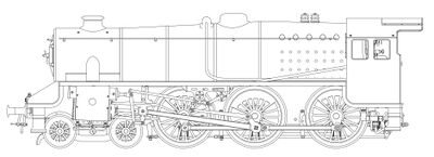
LBSC's Doris
Jim Mullner
February 2022
Drawing Corrections
The information given in the Model Engineer articles is general pretty good but there appear to be issues in a few spots. Namely things will interfere if built to the dimensions shown. Here are a few of those areas that I was able to discern by modeling Doris in Solidworks.
- If you are actually going to build an LBSC design make sure to layout the entire project using 2d or preferably 3d CAD software to avoid nasty surprises during real assembly and testing.
Please use the 3d model files presented here to check your work and review the details provided in the Model Engineer magazine articles. I recommend reviewing the original instructions and then reviewing the 3d model to confirm.
Buffer beam and frame
If angle is used to connect the buffer beams to the frames, recenter the rivets and also be aware using the angles will cause interferences later. But these are minor.
Leading and Trailing Coupling Rods
Coupling Rod Thickness
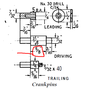
Crankpins
Feed Pump
Brakes
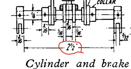
Middle Brake Beam
The Middle Brake Beam should be 2-1/16 inches wide, not 2.75 inches, to accommodate the above changes. See 3d model for details.
Drain Cocks
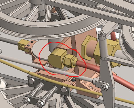
There were two issues here. First the handle on the tapered plug and the handle on the shaft must have the same distance between centers – use 1/4 inch. Second, the shape of the connecting rod had to be altered to let the shaft go through the approximate location in the bogie given without hitting and screws (almost flipped its profile) – the hole in the connecting rod should probably be slotted. See 3d model for details.
Bogie
By lowering the connecting rod shaft for the drain cocks you need to put a clearance cut in the bogie bolster. See 3d model for details.
Boiler
There are a number of issues here but the biggest is the vertical pitch of the firetubes. It really must be 3/8 inch (not 7/16 BARE). This will setup the upper features correctly.
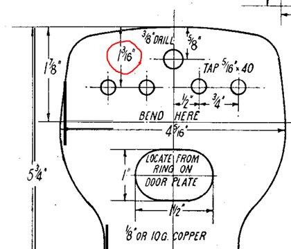
Backhead
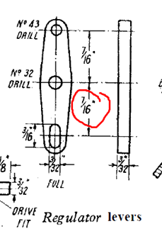
Regulator Lever
Documents
- Doris Erection Drawing by Jim Mullner
- Exploding view of Mechanical Lubricator for Doris by Jim Mullner
- Exploding view of Cylinder for Doris by Jim Mullner
- Doris 3D Model in STEP Format
- The 3d model can be opened and viewed using this free viewer: https://www.edrawingsviewer.com/frequently-asked-questions
- "Doris: A 3-1/2 inch gauge L.M.S. Class 5 Loco", by LBSC, Model Engineer (PDF)
- British BA Threads
- Sheet Wire Gauges
- Steam Unions
- Union Nuts & Fittings
