Gumz Turret Valve
From GGLS/Archive.org
The Gumz Turret Valve
by Charlie Reiter
The Gumz Turret Valve takes its name from its designer Dave Gumz. Dave is a life member of the Golden Gate Live Steamers and is one of the good guys. One of those fellows that is always ready to help if ask but would not interfere by venturing the un-requested opinion. He has retired from “hernia gauge” but is still ready to help with his great experience in steam engineering.
Dave is a meticulous builder whose career in scientific systems made him a very precise designer and machinist. When Dave started building his first locomotive, a narrow gauge Mason 2-6-6, he need a turret valve. Working in the science discipline he was familiar with Hoke Teflon sealed valves and used a simplified version of them in a turret array. That 4 valve array was installed in 1981 and has not required any maintenance in the 4300 miles he put on the locomotive. Click Here for a picture of that original valve array.
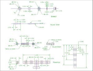
Below is a drawing for the basic valve and both a 4 and 5 valve manifold.
I made enough parts for 4 valve clusters at the same time so I tried to optimize batch work. But my description is focused doing all the operations on one part at a time rather than groups of parts.
Valve Bodies
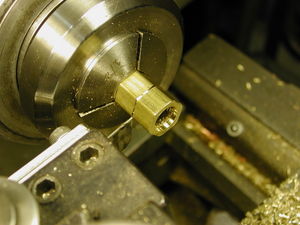
The heart of the design is the valve body. I chose to make these of threaded brass rod, 3/8-24, rather than thread the 3/8 section. I cut blanks 1.25” long. Leave enough extra for cleanup if your cuts are rough or out of square.
I have a collet lathe, and for making fittings nothing is better but, you can get great performance out of a 3 jaw chuck by using a threaded split bushing. This is a straight bushing threaded and then split with a fine saw down the side so that it tightens when clamped in the chuck or in a collet. I used one for making the valve stems. Holding in 3 jaw chuck without a bushing has the liability of damaging the threads due to the higher pressure of the jaws line contact.
So now that you have a valve body in the lathe, turn it down to .248” for a length of .875”. The under ¼” size is so that there will be room for the braze material in the manifold assembly.
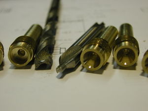
Then turn the blank around and turn down the other end to .312” for .125”length. Now on the same end center drill with a ¼ inch diameter center drill until the diameter is just starting to raise an edge. This is to support the next operation. Grind a ¼” drill for a flat bottom and be sure to dull the cutting edges to keep it from hogging in. Use this special drill to make a square bottom recess to a depth of .125”.
Next use a #21 drill and drill .75” deep measured from the front surface. This is where the 10-32 threads go, but before threading drill the rest of the way through with a #36 drill.
Then thread 10-32 down about .625”. Now the valve seat is made by drilling to a depth of .813” from the front surface, with another modified drill bit. The drill is a #21 but the end is ground to make a flat bottom. It should just remove enough to create the flat surface or more importantly the square edge at the # 36 passageway we drilled earlier. You don’t want to go to deep and being a little shallower could be useful if you need to clean up a seat in the future. I put a sleeve over the drill so I could drill to the same depth reliably.
This completes the valve body, excluding deburring. The front recess should have smooth surfaces at the edges and the remaining 38-24 threads should be clean with the start point softened. The ¼” ends of the valve bodies are intended to get threaded or connected with compression fittings, and if you have it all figured out it may be easier to thread them in advance.
Valve Manifold
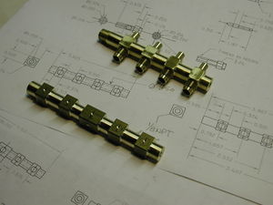
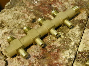
The valve manifold is a ½ square brass rod that I chose to turn to round between the areas that hold the valve bodies. It can be left square as Dave did on the first one or even could be made of round stock. The square is easier to fixture.
I made both 4 & 5 valve units and the layout for those is provided on the drawing. For turning the round areas I mounted the part in a collet, and supported the free end on a live center. I just turned to lines drawn on the part.
The 4 valve unit was made to go vertically and was threaded 1/8 npt on the top. The 5 valve unit was fit to an existing 4 bolt flange. The unused ends are threaded 5/16-27 for a plug or additional valve position.
The holes for the valve bodies are .25” and the passageway over the length was drilled .187”, so it would give a nice clean hole at the finish. Once the valve bodies are brazed in the part becomes difficult to clamp so the final cross hole was drilled ¼” with a hand drill, the part being set it in a bench vise.
Brazed Manifold
Once the bodies and manifold are done they can be brazed.
The fit should be a good sliding fit so the braze material can get through. After fluxing everything I set the valve bodies in the manifold leaving them slightly away from the front surface so I could get a little braze material in there if there was any problem but the material ran through and the bodies would suck up to the surface.
I used a 1/32” silver solder wire which makes it easier to control. Keep the heat on the big part and probably using propane is a good approach.
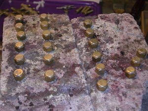
I had sandblasted the manifold to see what it would look like but I taped everything and sand blasting it again to clean everything up after it was done. It gives it a nice almost casting look.
Valve Stems
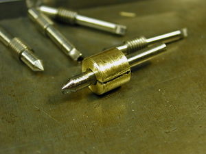
Valve stems are made of stainless steel threaded rod. Mine were made of salvaged 10-32 bolts. 8-18, the generic stainless for screws, is a good grade of stainless for machining.You of course could use brass or threaded bronze rod if you like.
I used a threaded bushing to protect the threads mounting that in a collet. I cut the shaft size to 1/8 for .625” long. I decided this was a good time to drill and tap for the bolt that retains the handle. If I should break off a tap then I would not have a lot invested in the part yet. Maybe drilling and threading should be the first step. I then turned the valve stem around and cut the unthreaded section at .156 at leaving a .25 long threaded section. Next the 60 degree angle on the end. I got away with using an angled cutter rather than using the compound. I held it by the threaded portion in the bushing to keep it as stiff as possible.
Squaring Stem
The square valve handle mounting section was cut using a collet spinner on the milling machine. This allowed me to hold the 1/8 shaft and keep support close to the tool. Of course for a few they can even be filed to a close enough square. Once the handle is on you will never see it again.
Handles
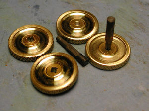
Handles were made by cutting a piece of 1/8 thick sheet into squares about .875 square. These were then stacked in groups of about 5 or 6 and “pressure plated” between centers. I then mounted the round blanks in a collet with a stop in it, a pot chuck would be the same, and drilled a center hole at .093. I then mounted the disks on a pin protruding from a piece of .875 rod and with a little cap over the pin to allow the tailstock to clamp the disk knurled the edge. Then back to the collet to add detail by thinning the thickness, leaving a thick center and outside edge. The square holes were broached with a .093 square piece of tool steel .75 long. It was turned to a .093 round lead in with an angled cutter that left “teeth” at the corners. This was hardened and then with a lot of lubricant pushed through the handle holes in an arbor press.
The square holes were then dressed up with a little square file. The disk wheels were then further detailed by adding six 0.125 holes. The holes were made using a drilling jig that is like a cup with the holes in the bottom. Once the wheel is set in the jig the first hole is drilled and a pin inserted to index it. The rest is drilling and deburing. I did try threading the valve rod and threading the handle to fit, then using the center screw to lock it but did not like the resulting fit.
Valve Seal
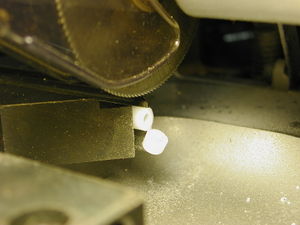
The valve seal is a piece of ¼” Teflon rod 1/8” long with a 1/8” hole drilled through the center.
Teflon is soft and deforms easily, so I drilled to a depth of only about 1” length at a time. I was concerned about the drill drifting off center in unsupported material.
Then I used a small saw to cut the 1/8” pieces.
Parting Bonnet
The bonnet is made in two parts.
Cut the ½” hex stock to the .312” length first. Then drill and tap it to 3/8-24.
I drilled and then parted off with a thin blade, but as you drill deeper all it takes is a little chip under one cutting edge and the drill wanders off the center. So drilling and threading individual pieces improves the quality.
Brazed Bonnets
Now the caps get fluxed and silver brazed onto the nuts.
After cleaning them up, mount a piece of the 3/8-24 rod in the chuck. Screw a bonnet on and using a center drill and drill put a #29 hole through the bonnet.
The hole will come out on the true center, since it references the threaded feature.
Final Assembly
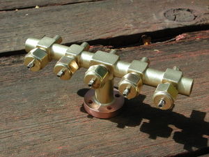
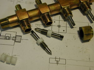
This shows how all the pieces fit together.
After all that work it's a nice feeling to see it all go together.
To connect the valves to the various points Dave simply had added a 1/4-40 mpt union to each of the tailpieces. Since I like to make as much as I can myself I chose to make little unions as integral fittings. The first ones were made as little flat ended ferules with nuts that had a 1/4-28 thread in them. That worked well except the ferules connected to the inside of the piping by brazing. The nut is truly captive stuck between the ferrule and the pipe. All that piping was 3/16 inch except the whistle valve which threaded on directly with a coupler. The next installation was improved by adding short lengths of 5/16-24 thread to the tailpieces. While a little touchy to braze on, it allowed ferrules to be made that would slip over the end of the 3/16 copper tubing, and the nuts could be slid up the pipe afterward. All of this is straight forward lathe work.
The valve group works really well and the only leaks were at the packings. Those were stopped with a quarter turn tightening. The flat face connection of the unions, seal reliably and don’t require any pull back when disconnecting.
I have been extremely pleased with the performance of the original unit built by Dave Gumz (seen below) on his Mason and with my version as installed on my Shay.
