Greenly’s Hudson
.jpg)
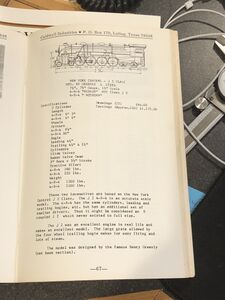
Henry Greenly designed this 1.5 inch scale, 7.25 inch gauge interpretation of the famous American 4-6-4 Hudson J2 between 1935 and 1937. Greenly's design could be built as a 4-6-4 or as a Northern 4-8-4. At least one 4-8-4 model was built from these plans.
Caldwell Industries of Luling, Texas offered a set of drawings and castings (110 parts) in the 1970's.
3D Model
Jim Mullner
March 2022


Drawing Corrections
Eccentric Rod Length
Error noted on drawing AH8 - eccentric rod is 11-1/8 inches long not 10-1/8 inches long. I spent about 3 hours chasing it down today. I would hate to build this without first modeling it entirely in CAD. I had to scale the print to find the error.

Rod Interference
Found another fairly obvious interference issue. The reversing shaft interferes with the coupling rods (see drawing AH14).
I had just completed an animation of the Baker valve gear when I noticed it. The Baker valve gear was a quality job except for the eccentric rod and drop arm.

Axle Box Pivot
AH 6 - How long is the axle box pivot rod? This has the spring on it.

The spring for the axle box seems off. No. 8 gauge is either 0.129 inch diameter or 0.169 inch diameter. If there are 10 coils over 1.5 inches then the spring is already fully compressed (eg 10 x 0.129 inch = 1.29 inch)
Hornblock Screw
AH 6 - Is the hornblock screw modeled correctly - see the countersink in the main frame.

Gear Frame
AH 1A - Does the gear frame get a clearance cut to let in the main frame or vice versa?
AH 1A - The gear frame interferes with the leading 10 inch wheel, must have to cut away interference in gear frame.

Mainframe Cross Members
AH 12 & AH 1A - How do the angles and channels connect to the main frame, girders, buffer beams, etc. I do not see any rivets.
AH 1A - What is diameter of holes in front buffer beam - are these for buffers?
AH 1A - How are the 3 x 0.5 inch trailing frame bars (and the angles) attached to the main frames - rivets, welding, etc.?

Front Bogie
AH 1A, AH 7, AH 12 - No spring info is provided for the front bogie. There are a total of 8 springs in the 1/2 inch square hole. Spring info is not clear on any sheets.
AH 7 - Bogie axlebox probably needs same relief chamfer as hornblock. For this add to both top edges to keep one style of part (no mirror).

Rear Bogie
AH 12 - the 1-1/8 inch dimension for the ball hitch needs to be 1-3/16 inch for there to be a 1/16 inch recess into the bottom of the mainframe back floor. Or that floor is not 3 inch off the rail level.

AH 12 - No suspension spring info is given for the trailing bogie - four springs requiredd in axleboxes, two in bumpers.
AH 12 - It is not clear how the rear frame 1/2 inch thick members are connected - by rivets or welding
Rear Frame
AH 12 & AH 22 - Rear frame stay with 1/2 inch diameter hole is not located fully on AH12. No height info. This seems to be for a steam brake that is not fully detailed either on AH 22.

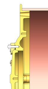
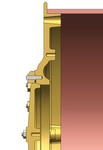
Smokebox Door
This is not an error, per se, but worth noting. Greenly's drawing number AH20 is a bit sparse, but it looks like there are two working dogs, and those are at 3 o'clock and 9 o'clock. The other dogs are just lining up against the edge of the door and do not actually clamp it down. Perhaps the intent was to make it less tedious to open the smokebox door. British prototypes use a single rotating locking mechanism on the center of the smokebox door, so it appears this was Greenly's solution to simplify access while retaining the look and feel of the American prototype.
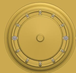
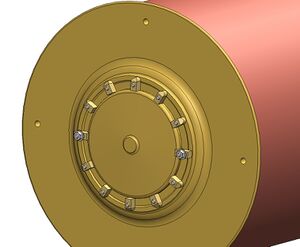
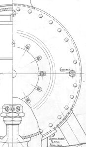
Detail of the Smokebox Door of Henry Greenly's 4-6-4 Hudson drawing AH20.


Documents
- Hudson Cylinder Assembly 3D model in Parasolid (X_T) Format
- Hudson Design, STEP Format
- Hudson Cylinder Drawings (PDF)
- Greenly's Drawings
- Greenly Hudson in Fusion360 on Github
Gallery
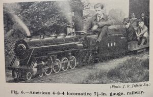
An American 4-8-4 Northern in 7-1/4 inch gauge built from Henry Greenly's Hudson/Northern plans.
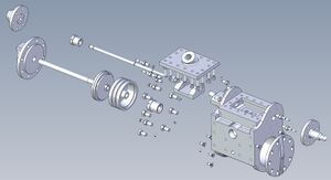
Exploded view of the cylinder. This can be done using the eDrawings viewer from the parasolid file.
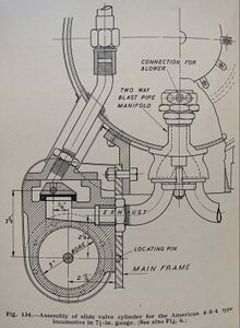
Assembly of slide valve cylinder for Greenly's American 4-6-4/4-8-4 locomotive in 1.5 inch scale. From "Model Steam Locomotives" by Henry Greenly, Oct 1962 edition.
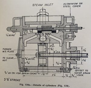
Cylinder detail for Greenly's American 4-6-4/4-8-4 locomotive in 1.5 inch scale. From "Model Steam Locomotives" by Henry Greenly, Oct 1962 edition. From "Model Steam Locomotives" by Henry Greenly, Oct 1962 edition
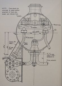
Smokebox arrangement for a 1 inch scale 4-6-4 by Henry Greenly. From "Model Steam Locomotives", Oct 1962 edition.
Smokebox arrangement for a 1 inch scale 4-6-4 by Henry Greenly.
Greenly Hudson & Northern was offered as drawings and castings by Caldwell Industries of Luling, Texas in the 1970's.


