Electric Bell
by Arthur Pettis and Paul L. Deverter II
Live Steam Magazine, March 1980
For some time, I had been looking for a compact and easily constructed bell to use on 1-1/2 inch diesel locomotive. The scale size bells do not have the proper tone. I have seen solenoids and automobile flashers used to strike ships bells, but the current draw is quite high.
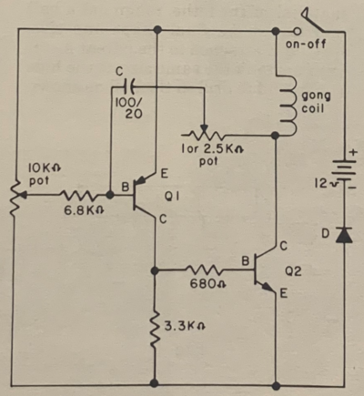
Arthur Pettis of the Southwestern Live Steamers designed an electronic circuit which will work with any size vibrating bell or gong from 2 to 12 inches and works equally well on 6 or 12 volts. This is his circuit.
It is a form of oscillator and the current through Q2 is intermittent. The gong rate is adjustable, as is the striking power. The current can be adjusted to be less than 0.9 amp at a gong rate of once per second and the gong can still be heard at 150 yards. Thus the power source can be a small Sears Garden & Tractor battery, a motorcycle battery, or even a 6 volt latern battery.
All of the circuit components are available at Radio Shack. SInce there is no high power of requency involved, most any general duty transisitor can be substituted. A breadboard circuit can be powered with an HO gauge power supply 'til the desired gong rate and striking power (intermittent current) is achieved. A small 3 amp meter, temporarily connected in series with the battery, is useful to adjust the current to a minimum.
Using the components shown, I settled for an intermittent current of 0.9 amp at a frequency of one per second. The 10K pot was set with the resistance between the wiper and E of Q1 at 750 ohms and between the wiper and C of Q1 at 9250 ohms. The 2.5K ohm potentiometer was set at 700 ohm between the capacitor and C of Q2. A lower resistance here results in a higher current draw. If the current draw is too high, then Q2 will get hot and will undoubtedly burn out if not cooled with a heat sink.
The diode is optional. I put it on my circuit to protect it against hooking up the wiring backwards. If you use color coded wires, it can be omitted.
- R - all resistors are 1/4 watt. Larger wattages are fine. The variable resistors are printed circuit board trim potentiometers, about the size of a penny.
- C - 100 microfarad, 20 volt; 80 microfarad, 16 volt will work
- Q1 - 2N458 was used because it was available, any medium mpower PNP will do
- Q2 - 2N3055 (NPN) readily available, high power, heat sink not needed if current is kept below 2 amps
- D - general purpose 1 amp silicon or better. Optional, see text.
My gong is 6 inches in diameter and came from the Surplus Center. The cost was $6.95 (Security Alarm Bell, Catalog #29-906, 12 volt, 300 milliamp 6 inch O.D.). The Radio Shack gong is 8 inches, and was too large to hide in mu locomotive.
After assembling all the components, and arriving at the trimp potentiometer settings desired, the next step is to shrink all of the components into a small package. As you can see, I was able to saw out a piece of blank and prepunched printed circuit board to fit under the dome of the gong and squeeze all of the components onto it. I even managed to arrange the trim potentiometers so they could be adjusted from access holes in the base of the gong. However, I have never had the occasion to adjust them.
Gongs generally come with an interrupter circuit, so that when voltage is applied, the plunger will reciprocate continuously. THis is done by using a small leaf with a contact point which is flexed by the plunger. Either bypass or short out the interrupter circuit. Some gongs have two coils. If it is a 6 volt gong which you are going to use on 12 voltes, reconnect them inseries. If it is a 24 volt gong, and you are going to use 12 volts, then reconnect them in parallel. However, since the current draw is so low and only about once per second, instead of 60 cycles, you will find that the coils won't overheat if you don't reconnect them.
When soldering the transistors, use a light touch with the soldering iron to prevent ruining the components. A heat sink should be used on the pins between the soldering iron and the transistor. If you don't have one, use needle nose pliers held on the pin by an assitant or by a rubber band.
The unit is quite rugged. Although not essential, the gong should be mounted with the plunger vertical and striking upwardly. The only problem encountered was an intermittent cut-out when riding my locomotive. I thought it was the cheap toggle switch I used, but when I stopped the engine, the ringing resumed. Careful investigation showed that the mounting of the bell was not rigid, and at certain speeds, the gasoline engine caused the bell to vibrate at such a frequency that the plunger couldn't move. Additional bracing soon set matters right.
