Donald Yungling
Fitchburg Northern
Donald Yungling shared his experience building a Fitchburg Northern on the associated group.
January 2020
Hello, my name is Donald and I am building a Fitchburg Northern. It started out with my helping my friend Marty build the FN. I would machine the parts he was not comfortable tackling himself or walk him through the process on a particular part, or parts. Unfortunately Marty's health has failed and he is no longer capable of performing machine work. He has given the FN project to me and I am now in the process of continuing with the build.
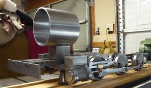
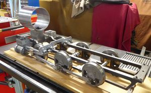
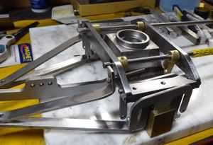
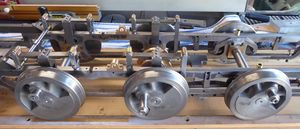
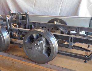
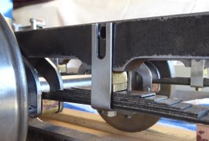
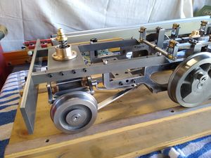
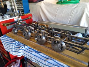
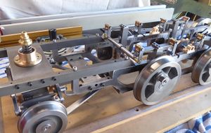
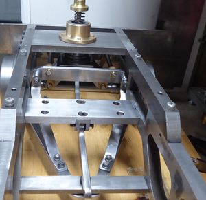
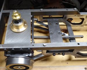
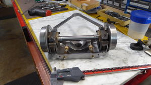
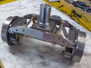
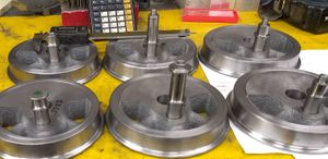
The two attached photographs illustrates progress as of about 2 months ago. Since that time Marty had made the driver leaf springs, driver spring seats and some brake parts. Currently those are in a box awaiting my attention and will be presented to you guys when their turn comes up.
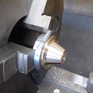
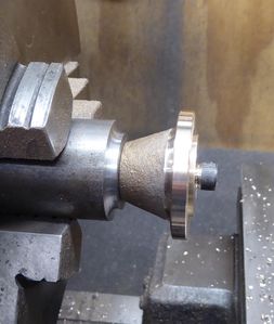
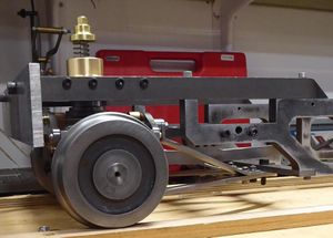
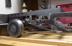
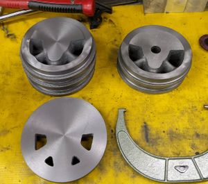
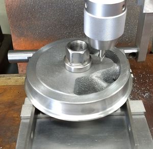
At this time I am building the lead truck. The wheels, center bolster casting, pedestals and swing links have been machined.
I may also add additional videos to my YouTube page of some of the machine work.
Here is Marty operating his beautiful Allen Models on the SVLSRM railroad.
<videoflash>oJn-bPm8OBk</videoflash>
My YouTube channel with some FN machine work
I posted some photographs of some of the various steps in the driver and crankpin build of Marty's FN that I am now building. The photo's are in the Album Marty's Fitchburg on this site. The photo with the quartering fixture is staged. The actual assembly is on a press. First step is to press one driver on about half way. Then an alignment bushing centers the driver to the fixture and the pre-drilled hole aligns the crankpin. Then the axle boxes and eccentrics are added as needed. Tho other driver is aligned on the top plate again using a bushing for the axle center and the crank pin fits in the hole in the upper plate. Once the second driver is on about 1/2 way the alignment pins are removed and the drivers are pressed home. No keys or keyways are needed.to quarter the drivers.
The press fit is more than adequate to hold the drivers in position and to keep the drivers from spinning on the axles. We have used this method on numerous locomotives including my GS-1, and my dad's cab-forward. It has proven to be a very accurate method to quarter drivers.
I made the crank pins 9/16 inch diameter and they, as well as the retaining nuts and washers, are made from 303 stainless.
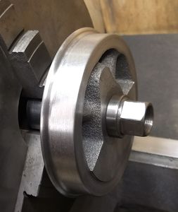
Meanwhile lead truck progress is being made. The axle, axle boxes and wheels were finished up this afternoon and the lead truck wheels were pressed on the axles.
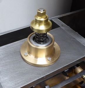
The springs that Marty had purchased for his FN were 1/2 inch diameter, 1-25 inch length and .047 inch diameter wire.
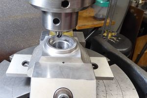
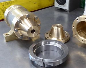
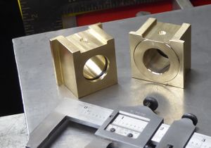
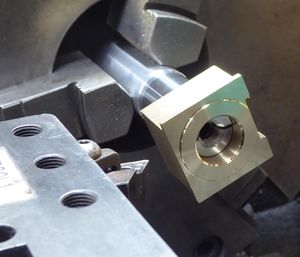
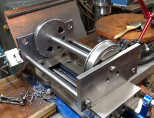
To machine the o-ring groove and face of the axle box I made a split shaft and used a 3/8"-16 Allen set screw to hold the box firm while machining took place. The o-ring is inboard side to keep debris out and force the oil against the thrust side of the axle box. We used the same method on the driver axle boxes.
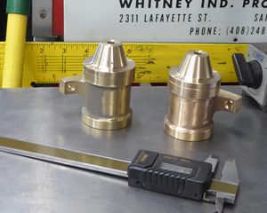
The springs Marty purchased for the lead truck were 1/2 inch diameter so I made brass inserts and silver-soldered them to the lower spring seats. The upper spring retainers were per the drawing with the exception of the diameter increased to better match the springs.
I prefer the largest practical axle diameter so the swing bolster was relieved in the axle area and the center section of the axle turned to .625 inch instead of the 1/2 inch size specified in the drawing.
When first assembled the pedestals did not sit flat, inspection found the ends of the cross supports weren't quite flat so about .010 inch was removed from the inside face and now all is square.
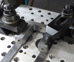
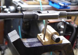
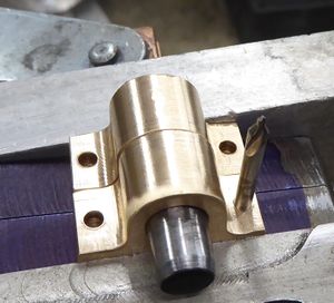
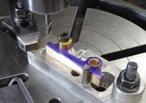
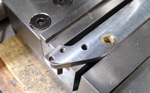
While on the lead truck I squeezed in machining the pivot blocks for the brakes and reverse shaft as these parts are needed to complete the frame.The blocks were then clamped to the end of the frame, an 1/8" center drill spotted the holes and then the blocks acted as drill and tap guides.
I designed and built a separate pivot arm support that mounts under the cylinder block. For me this will make setting up the spring rigging an easier task without having to wrestle the frame with the cylinders installed. Time will tell if this was a viable option.
On the prototype the side stays were generally left exposed as they were tell tale stays. Those stays were hollow and if one broke a small steam leak would become obvious. Most modelers make fake side sheets to replicate that detail.
On our models room for the jacket and personal preferences should be your guide. If it looks like it would work, I think my preference would be to extend the jacket to match the bottom of the cab floor.
My lead truck radius bar mounts underneath the pivot bar as shown in the attached photo. I do not think there is enough clearance above the bar. I also realized the pivot bar sits 1/4 inch lower on the water-jet frame than shown in the built up frame drawings. The higher either the pivot bar or the radius bar is mounted the closer to the equalizer lever they become. I had some brake cross bar clearance so I ended up making the brake shoe hangers 1/4 inch longer.
