Design, Care and Feeding of Check Valves
From Golden Gate Live Steamers, Archive.org
Technical Summary by Stephen Vitkovits, August 2003
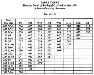
Our speaker for the August 2003 meeting was Bob Cohen whose topic was THE DESIGN CARE AND FEEDING OF CHECK VALVES. The material Bob presented was originally published in the April 1979 issue of Live Steam Magazine, page 19 by Everett Clem. The information was in three tables with no accompanying text. Bob's contribution was to add explanatory notes, correct Figure 1, and expand the discussion to the maintenance and repair of check valves.
What is a check valve? Anytime a closed vessel is filled with a fluid under pressure; some means must be used to prevent the escape of the fluid once the pumping action has stopped. Two model engineering examples come to mind immediately viz. steam boiler and air brake tank. Thus, check valves (or clacks) are used to insure flow in a given circuit in one direction only. A good analogy is the diode in an electrical circuit.
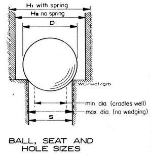
Although there are many types of devices used to control the flow through a check valve, Bob focused only on those valves using stainless steel balls. Inline valves have the inlet and outlet bores coaxial and may be mounted either vertically or horizontally. The familiar locomotive clack has the inlet vertical and a horizontal outlet connecting directly into the boiler shell. Usually the back-pressure keeps the ball in its seat, but in some circumstances it's advantageous to employ a spring to hold the ball in place. Note in Figure 1 the dimension H1 which is to be used if the ball is spring loaded. Check valves for lubricators are usually mounted upside down so use a spring to keep the ball against the seat.
An important dimension in a check valve is the distance the ball rises out of its seat. The correct amount of lift depends on the application. In general, check valve lift for mechanical and steam pumps is between 1/8 and 1/6 of the ball diameter. Check valves for injector service use the highest lift: 1/3 ball diameter.
Check valve design starts with selecting the ball seat diameter S. See Figure 1. Although the value may be calculated, it's quicker to survey the published designs for typical sizes for a given scale. Keep in mind that check valves should (1) be designed to give minimum resistance to flow in the easy direction, (2) have infinite resistance in the back direction, and (3) be easy to service.
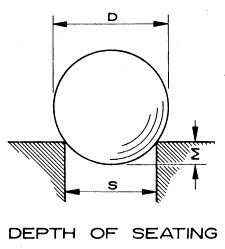
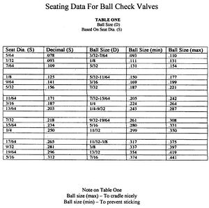
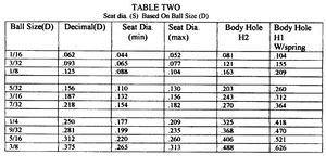
Tables 1, 2, and 3 along with Figures 1 and 2 provide all the information to design a check valve.
Consider the following design example.
- Service: Injector
- Seat Diameter S: 3/16 inch
From Table 1 find the line for seat = 3/16 inch under Column S. Move right to Column Ball Size D and find the ball diameter of 1/4 inch. If starting with the ball diameter use Table 2 to determine the seat diameter. Next, go to Table 3 and find the depth M to be 0.042 for a 1/4 inch ball sitting in a 3/16 inch seat. That means the top of the ball is 0.25-0.04 or 0.21 above the seat surface. This dimension along with the lift desired will determine where to place the pin that limits the ball travel. In this case, the lift will be 1/3 of 1/4 or 0.08 inch. Therefore, the stop pin must be placed so that its point of tangency with the ball is 0.21+0.08 or 0.29 inches above the seat surface.
Refer to any text on model engineering for typical valve construction. The one-piece body types have minimum joints to seal, but may require making a "D"-shaped bit to form the seat. Further, should the seat need attention later it may be difficult to correct the problem. Splitting the valve body at the seat surface creates another joint to seal, but has the advantage that the seat is easily made and should the seat need attention it is very accessible for repair or replacement. The diameter H2 is found in Table 2 and for a 1/4 inch ball it's 0.325 inch.
After the valve is constructed, the ball needs to be seated. If the hammer tapping method is selected, make a bushing that fits inside the body to guide the punch while it is tapped so the ball is hit squarely in its seat.
References
- "Ball Check Valve Seats: Data Sheet", Everett W. Clem, Live Steam, April 1979
