Centerville and Southwestern Railroad
Description
The Centerville and Southwestern R.R.'s
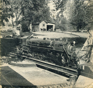
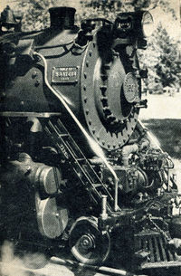
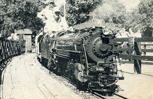
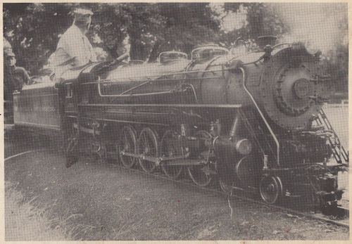
Two Inch Scale 4-8-4- Steam Locomotive
by H.E. Becker
All Photos by Bruce Nett
The Miniature Locomotive, July-August 1953
The Centerville & Southwestern was first thought of over tweny years ago (about 1933). Time went on and finally in 1938 the first rails of the 9-7/16 inch gauge line were laid. Previous to this much thought and study went into the location and grades of the line. Cropland of our farm had to be considered. A southwesterly route, more or less following field boundaries, was selected. This direction plus Roseland's original name of Centerville gave the railroad its title.
Standard 8 pound rail was fastened to 3 inch by 3 inch ties with 1/4 inch by 2 inch railroad spikes. Cinder ballast, one foot deep, was used, but it "powdered" to quickly and a 4 inch layer of 3/4 inch gravel stone was tamped under the ties. The first winter taught us the importance of good drainage. From then on standard ballast consisted of 10 inches of packed cinders placed on a well crowned subgrade and followed by 4 inches of 3/4 inch sharp crushed stone. The sharp stone held the track in surface and in line better.
Absolute minimum radius on the C&S is 100 feet, which is used only in yard switches and tracks. All main line curves are 200 feet or more, except for Horseshoe Curve, which is 125 feet. Elevation on curves varies according to maximum speed allowed. Curves are laid out with spirals at each end.
Rails are spiked to exact gauge except on curves where it is widened automatically by "Y" shaped track gauges. All of the track work, done by the farm employees was sandwiched between regular farm work.
The first summer was an experience with sun kinks. We remedied this by removing splice bars, setting the proper gap in the joints according to temperature (1/16 inch at 70 deg. F. for fifteen foot rail), coating the bars and rail ends with a special rail joint compound put out by the Dixon Graphite Co., and tightening the bolts up good and snug but not tight.
The wye at Peach Tree Junction (named after an orchard), the end of the line until 1949, is 8/10 of a mile from Centerville station.
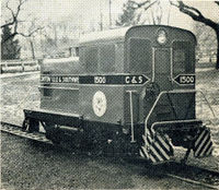
Practically all of the original line was built with the aid of an 0-4-0, powered by a second hand motorcycle engine, and a 14 foot wooden gondola. This locomotive and car, with its straight air brakes, many times attained a speed of over 40 m.p.h. Incidentally, the frame of this locomotive, twice re-built as a battery electric, has just this year (1951) emerged from the shops as an 0-4-0 diesel switcher painted a bright red.
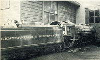
Meanwhile, during track construction, Mr. H.B. Ayers, retired president of the H.K. Porter Locomotive Company of Pittsburgh, with the aid of Mr. J.B. Innis, then the vice president of the American Locomotive, as consulting engineer, was proceeding with the design and construction of the 4-8-4 "Pocono" type live steam locomotive in Bridgeport, Conn. Our ruling grade of a little over 3 per cent prompted Mr. Ennis to recommend a 4-8-4 rather than our original idea of a "Hudson".
There is a counter-part to the ruling grade of 3 per cent on the other side of the hill which is 2 per cent on a reverse curve. The Horseshoe curve prevents "making a run" for the hill. There is just one level piece of track and that is on a curve and not more than 200 feet long. All new construction is held to 1 1/2 per cent.
The boiler for this locomotive is the second all-welded locomotive boiler built in the United States. Alco built the first such boiler for the Deleware & Hudson R.R. and later the one for the C. & S. The shell and wrapper sheets are 3/8 inch; the crown sheet, inside wrapper and tube sheets are 1/2 inch.
Originally built with a super-heater it has 1-1/2 and 3/4 inch tubes. The superheater was not very successful, and has long since been removed. The operating pressure was upped from 125 to 150 p.s.i. with ample safety as the boiler is made to the A.S.M.E. code and tested to 450 p.s.i. The boiler is absolutely free of scale because rain water, collected from the round house roof and stored in an obsolete 2,000 gallon milk tank, is used exclusively. This locomotive can haul 14 cars carrying more than 120 passengers over the entire line.
The firebox is equipped with shaking grates. The original malleable iron grates did not stand up well as there is very little room for accumulation of ashes under them. Since the war (World War II) we have found a high temperature alloy that has ten times the service life. This material is also used in the arch.
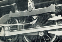
Drivers on the locomotive are cast steel centers with tires made of locomotive tire steel. What little wear there has been on the flanges (mainly on the number one pair) has been automatically taken care of by the use of flange truing brake shoe used on the drivers. Flange wear is kept to a minimum by keeping the speed down to 5 m.p.h. on Horseshoe Curve, equalizing the number of trips in either direction through the loop, and correspondingly low speeds on some of the other curves.
Top speed of Engine 1501 is still unknown although it has been as high as 25 m.p.h. Turning a rail over is the chief danger of high speed rather than having the locomotive roll over. To operate the 1501 one must have the skill of a full fledged locomotive engineer. Watching the water lever is of course, important but on the C & S it is more so because of the comparatively steep grades. If there is too much water in the boiler going up hill there is danger of priming; conversely, if there is not enough water going down hill there is danger of burning the crown sheet or even an explosion.
In all probability Engine 1501 works much harder than any other miniature locomotive. Consequently, care of the fire requires ingenuity as to how much coal and when and where to use it. If the engineer is to get over the road without a steam failure he must operate the engine in the most efficient manner in spite of the urge to "hear the exhaust". The water level, the condition of the fire and the position of the throttle and reverse lever are governed by each other.
The engineer must use the air with judicious caution and in the proper manner so that the passengers are given a smooth, pleasant ride. He must also watch his air pressure gauges to always be certain the train is at all times under control. It might be well to mention here that a little over 200 feet is needed to make a service stop with eight loaded passenger cars going 12 m.p.h. on level track.
The tender is filled with water on every other trip regardless of the amount needed and ashes are dumped on the alternating trips.
On the C & S the engineer has just one responsibility and that is to look after the engine at all times exclusively. In case of mishap of any kind he has orders not to leave the locomotive unless it be an extreme emergency (which has never occurred).
The history of the air compressors is quite a story. Originally they were cross compounds and as far as pumping ability they were just above being a flop. Twenty five pounds was tops and that disappeared at the flick of the brake handle. We then designed a 2 cylinder duplex pump which had considerable more volume but a maximum of 50 to 60 p.s.i.
New heads were designed for these and reconverted to two single pumps. Some of the credit for the success of these compressors must go to Mr. Henry Greenly for his method of making small piston rings which are used in the distributing valve. Each compressor is capable of putting out 150 cubic inches per minute at 90 p.s.i. Train line air pressure is maintained at 70 p.s.i. by a feed valve and equalizing reservoir.
The first six cars were designed and built by Mr. Berthold Audsley with a built-up steel under-frame made to look like the older heavyweight Pullmans, up to the floor level, and ride on Pullman type six wheel trucks. Later, the C & S shops designed and built ten more similar cars except that the under-frame is of all-welded construction and they ride on the newer type Pullman four wheel trucks. All parts and equipment of the cars are interchangeable, including the four and six wheel trucks. All but two comfortably carry 6 to 8 adults. The other two Pullmans have four parlor car seats each.
A hopper car, of all-welded steel construction, weighs 1355 pounds and has a capacity of 4800 pounds with 44 cubic feet. This car rides on modified standard four wheel trucks. The caboose, designed as an added attraction, is also useful for carrying tools, etc. Special archbar trucks were made for it.
All cars are equipped for automatic air brake operation with clasp type brakes, reservoir, triple valves, conductor's valve and "glad hand" air hose couplings as well as type D couplers. Also push-pull spring draft gear, safety chains and a hand brake. The air brakes operate exactly as their full size brothers do--a reduction to train line pressure applies the brakes.
Passenger cars are 14 feet, 6 inches long and weigh 1100 pounds each. They ride on roller bearings in swing motion, fully spring and equalized trucks, and are equipped with a second reservoir and equipment for electro-pneumatic braking as well as a signal button for the "peep" whistle in the locomotive. All wheels and axles are steel.
Power for the electro-pneumatic brakes is derived from a 30 ampere automotive A.C. generator driven by one of the trucks on a passenger car and connected through a rectifier to a common storage battery. A cut-in switch, operated by a Chrysler transmission governor prevents charging until a speed of 6 to 7 m.p.h. is reached. The "pull" of the generator car when charging is equal to the drag of one loaded passenger car. Jumpers carry the power from car to car. Each has 7 wires, viz; power, brake application, brake release, signal, ground, and two wires for eventual (we hope) electric door locks.
On the C & S there is absolutely no compromising with SAFETY FIRST.
After the decision to operate under a tariff, the first "paying" trip left Centerville promptly at 10:00 A.M. Saturday, July 31, 1948. The C & S continued to operate every Saturday thereafter to the end of October. It was quickly learned that a schedule be maintained. Engine 1501 and its train left Centerville station on the hour and half hour beginning at 10:00 A.M. through 5 P.M., except for the 12:30 and 1:00 P.M. trips at lunch time. The following year, Memorial Day, Fourth of July and Labor Day were included and the schedule on those days extended to 6:30 P.M. This schedule still prevails. There is no Sunday operation.
Completely rebuilt, from the frame up, Diesel Engine 1502 made its debut in 1949. This extra power and another crew relieved the 1501 of the 12 Noon and 5:00 P.M. trips.
In spite of the fare (adults--48 cents; children--24 cents) traffic increased to the extent that an extra had to be put on, running 15 and 45 minutes after the hour. As on the larger roads, the diesel has gradually come into its own. It is interesting to note that the 40 per cent adult--60 per cent children ratio has remained constant through the years.
At the end of the first year it was found that the railroad not only earned its way, but had made more friends and customers for the Becker milk business.
A 2,000 foot loop connecting the two ends of the wye, started in 1948, and finished in 1949, brought the total mileage of a round trip up to 2 miles. A turntable and round house are located at the Centerville end. Total track laid to date is just over 7,000 feet.
The round (square) house was originally built for the railroad, but as the machine tools were added it became apparent how necessary a machine shop was to the milk business. Consequently, it has been used over 90 per cent of the time for the maintenance of dairy and farm machinery--even to taking on the job of converting two large bottle washers to handle square bottles. The drawing board is also very often used for the milk business. In a way, the railroad has become a sideline to the round house. The coming of Engine 1501 indirectly saved the milk business thousands of dollars in repair bills.
Visitors who would like to talk shop are welcome, but more time can be given them if they will write ahead of time for a date, as very little time can be given on operating days.
The C & S isn't as wide; nor as long; nor is it narrow gauge. It is a true miniature railroad, and as such, of necessity, it is operated in the same manner as are its full size brothers. It is thought to be the only miniature railroad in the country that operates on a strict schedule; goes somewhere and comes back--not just around a loop; and runs through natural scenery, such as a trip on a full sized railroad would take you.
Essential Specifications
- Road No. 1501
- Built 1940
- Type 4-8-4
- Gauge 9-7/16 inches
- Cylinders
- Diameter 4-1/2 inches
- Stroke 5-1/4 inches
- Driver diameter 13-1/2 inches
- Boiler I.D. 15-1/4 inches
- Fire Box
- Length 26 inches
- Width 15-3/4 inches
- Tubes
- 18 of 1-1/2 inches diameter
- 20 of 3/4 inch diameter
- All 59 inches long
- Wheel Base
- Driving 45 inches
- Total engine 8 feet 7 inches
- Engine and Tender 16 feet 10 inches
- Length over couplers 19 feet 8 inches
- Weight in working order
- Leading truck 318 pounds
- Drivers 3905 pounds
- Trailer truck 749 pounds
- Total engine weight 4972 pounds
- Tender 2140 pounds
- Total locomotive 7112 pounds
- Evaporating surfaces
- Flues 7773 square inches
- Fire box 1502 square inches
- Total 9275 square inches
- Grate area 416 square inches
- Fuel - Soft coal
- Maximum tractive effort 1000 pounds
- Factor of adhesion 4.03
- Tender type - 12 wheeled
- 95 gallons water
- 150 pounds fuel
All locomotive and tender axles fitted with Norma-Hoffman double row self-aligning ball bearings.
Equipment
- 2 injectors
- 1 water gauge glass
- 2 try cocks
- 1 steam pressure gauge
- 3 safety valves
- 2 steam driven air compressors
- Turbo generator
- Air bell ringer
- Air sanders
- Steam blower
- Mechanical lubricator
- Independent and automatic air brake controls
- Fuesable plug in the crown sheet
History by Year
1952
Dick "PRR5406" posted on Chaski.org:
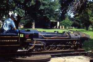
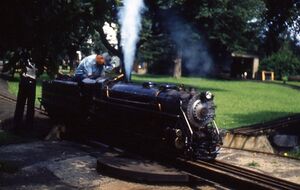
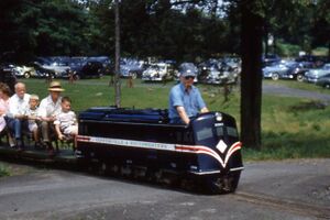
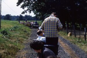
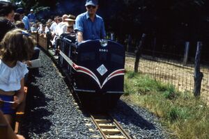
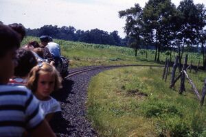
- I was cleaning out my garden shed and found about three-thousand slide taken by my wife's late Aunt, in the 1940's until around 1967. I did find one of an Erie Pacific under steam, and these as well. Apparently this is the Centersville Southwestern, around 1952. I know nothing about the railroad, other than it's a beloved layout in our hobby. Hope these images bring back some fond memories and comments from you guys.
1957
1960
2009
The following text and video is courtesy of Phillipsburg Railroad Historians:
- The Centerville and Southwestern is a 2 in scale, 9 7/16 gauge railroad owned and operated by the Phillipsburg railroad Historians in Phillipsburg, NJ. The C&S was saved from the Becker Dairy farm and was a famous NJ tourist attraction, today the C&S lives on thanks to PRRH. I also have a PRRH with a little C&S footage check that one out as well.
2011
The following text and video is courtesy of Phillipsburg Railroad Historians:
- The 1500 was the first engine built by Henry Becker for his 2 inch scale, 9 7/16 gauge railroad that ran on his dairy farm in Roseland NJ. After the farm was sold and the railroad disassembled the 1500 was sold to a railroad in Key West Florida. The 1500 was later acquired by the Lindfied's in Michigan. James Linfield has meticulously rebuilt this engine utilizing original parts where possible. On May 2, 2011 Jim brought the 1500 to the Phillipsburg Railroad Historians museum site (custodians of the majority of the remaining Centerville and Southwestern Railroad) to run his engine on our rails. Sister engine 1503 pulling a consist of Becker box cars (for passengers) ran the line with the 1500 following closely behind.
2009
What happened to Locomotive 1501?
Timetable

