Build a Power Reverse for Your Engine
Build a Power Reverse for Your Engine
The North American Live Steamer, March 1956
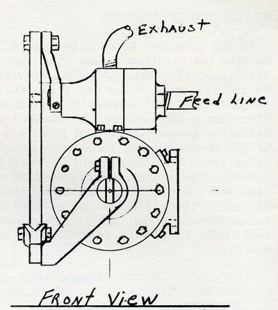
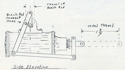
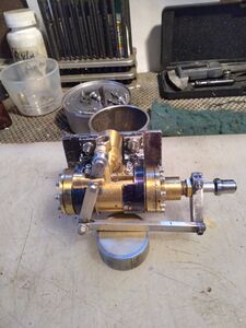
Here is a power reverse unit, patterned after the Franklin type. Designed and built to operate hydraulically, it will also serve satisfactorily on either steam or air. I built the unit for hydraulic action, using water direct from and at boiler pressure. Under these conditions it is very smooth in operation and neither kicks or drifts, and absolutely locks your reverse shaft arm to any cut off desired.
When using any power reverse mechanism in place of the manual operation, it is necessary to either replace your present reverse lever and quandrant with a smaller uit or drop your reach rod to a point nearer the pivot as the travel needed with the power unit is much less than the amount necessary for manual operation.
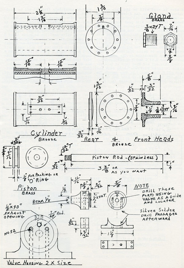
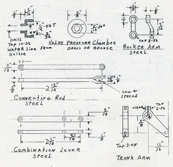
These drawings are for 1-inch scale. If you wish to construct it in 3/4 inch scale, merely reduce all cylinder and control rods by 1/4, but build the valve to the sizes shown. It will be hard to make the valve any smaller and have good operation. (Don't let me deter you in this though, if you can build the valve smaller, more power to you.)
There is not much use in using a lot of space in telling you how to do this job as each piece is simple in itself. Just follow the dimensions and it will fit together perfectly, and WILL WORK.
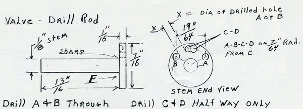
Make the valve as shown FIRST. Chuck a piece of 1/2 inch drill rod in the lathe, turn the stem to 0.010 oversize and about 1/64 inches short. Turn outside diameter to 7/16+0.010. Then with a sharp tool bit put a mark in what will be the face of the valve (shown as F in the drawing), half-way between the stem and outside diameter. Remove from the lathe. With your scribers set off and drill two No. 52 holes 19/64 inches apart center to center and about 1/8 inch deep. Now measure off distance X from both A and B holes and drill holes C and D, but only 3/64 inches deep. I woul duse a drill 4 or 5 sizes smaller for holes C and D, then enlarge them to bring Distance X to the same scaled dimensions as the diameter of holes A and B. If C and D do not touch together, chip out web. When this is done, replace in lathe, finish stem to size and face off F. Both should be very smooth. The stem can be polished by hand, but do NOT file or otherwise hand finish face F. it must be absolutely flat. Cut off to thickness 1/16 or 5/64 inches.
Turn valve housing, ream for stem, cut 1/2 inches 40 thread, face off and cut off to length. Make base as per drawing, drill no passages yet, and silver solder together.
Put in valve position so holes A and B are parallel with base, turn clockwise till valve port on the left moves an amount equal to its diameter. We will call this port A. Now using a No. 52 drill, drill to a depth of 1/4 inch. Turn back counter-clockwise till edge of drilled hole disappears. Now while the valve is in this position, (don't let it move) with a very sharp scriber, mark a short arc at the lower edge of the same port in the valve housing face. GOOD! Now turn the valve counter-clockwise until the scribe mark disappears from the upper edge of port A and just a frog's hair more for good measure. Now drill port B with the same size drill and to the same depth.
Now, how close did you follow directions? Fi when your valve is centered again you can see nothing through the valve port but a plank brass face and then by turning the valve that same frog's hair in either direction a port starts to crack open in one or the other of the valve holes, you win the hole in the don-nut, and I'll throw in the aforementioned frog's hair for good measure.
All that's left is to drill the exhaust port in the middle of the arc between ports A and B, come in from the top with your connecting hole, and tap for the size pipe used. (I used 1/8th or 5-40 thread.)
Drill the passages from the bottom to connect with port holes and with passages in cylinder. The rest of the job is fairly simple and with a good valve will give service indefinitely.
For piston packing, I used an O ring. They do not leak and are lubricated by the water. The main thing is not to fit them too tight.
I hope that I have made the drawings and explanation of the valve clear enough.
