Bill Oberpriller's Minnie: Difference between revisions
m (Dnevil moved page Minnie 2 to Bill Oberpriller's Minnie: Corrected the name of the project.) |
|
(No difference)
| |
Revision as of 13:17, 4 April 2016
Minnie 2 is a freelance 2-4-2 live steam locomotive designed by Bill Oberpriller.

Bret Kueber
Bret Kueber published the following photos of his version of Minnie-2 in 2000.
- Bill Oberpriller provided us with fantastic tech support via Email, and his products are first rate. Allen Models, What can I say, Gene has been extremely helpful, and my order ALWAYS arrived promptly. We never had a problem with any of the castings we purchased from him.
- # 13 (2-4-2) Coal Fired Columbia Class steam locomotive (Built 5/1999)
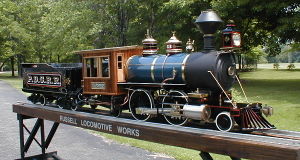
Engine #13's "Official" Builder's Photo (S/N 1001 Russell Locomotive Works). This is based on Bill Oberpriller's "Minnie-2" design.
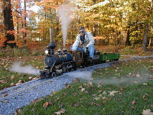
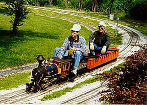
Bret Keuber's Minnie-2 Number 13. Fall running at Frosty Hollow on the P. D. C. R. R.


Jim Cook
Jim Cook published the following build log for his Minnie-2 in 2002.
Frame
This design first appealed to me because of its general shape. To me, it looks as if it is an engine from the last half of the 1800's. The diamond stack, large headlight and cow catcher gives it character.
From a first time builder's point of view, the 2-4-2 configuration fits well. All the castings will be from the tried and true Allen Models. The designer is attempting to reduce the number of parts. This should help keep the cost and time necessary to build the engine down.
I purchased the first kit. It is for the frame. The quality of the punched parts is very good. I was able to put both side rail together during a Saturday. The rear bearing housing, front bearing housing and equalizer and the front and back frame spacers have been received and completed. In the first picture you can see the front axle mounted in the equalizer bearing boxes.

The second picture shows the rear axle in their bearing boxes. These boxes are attached directly to the frame.

Note that the the axles (1 inch diameter) were machined on the ends to accept the drivers at this time.
I ordered the four driver bearing assemblies from a local bearing supplier and received them within a few days. The castings were ordered from Allen Models. I received all the wheels and valve rough castings by the end of October.
This is a view of the frame as of the end of the second week in December. The drivers have been machined and mounted on the axles. This is taken from the rear right.

I am now working on the valve gear. I have not finished the four eccentrics and straps. I have a Sherline lathe and mill that I use for the small stuff. I just got a 9 inch swing Jet lathe and I'm setting this up for the larger items.

To give you an idea of scale, the main drivers are 8.5 inches in diameter. I was able to turn these on my friend Jerry Johnson's large lathe. He also helped me broach the key slot and quarter the wheels.
The trailing truck has a nice set of spoked wheels whose axle runs in Oilite bearings. There is plenty of movement, left and right and up and down.

Boiler
Here the boiler has been set in place. There is a plate welded to the front face of the fire box that anchors it to the frame. The front portion of the boiler has a sliding fit into the smoke box. This allows movement of the boiler as it expands and contracts.
Note the fittings at each lower corner of the firebox. This will allow proper cleaning of the mud ring.
The smoke stack has been mounted but the top half has not been machined.


Ron Thibault
Ron Thibault published the following build log for his Minnie in 1998.
Tender Trucks
After talking to Bill, I decided to start construction of the engine with the tender trucks. He recommended Cannonball's Archbar trucks. After also looking at other companies castings, I agree! Cannonball has a good reputation, and their kit is also the least expensive! I like that combination!! The complete kit with all materials required is only $175.00 (they are also available RTR at $355.00). In addition I will order a wheel gauge template for 7.5" track, and the 29/32" drill needed for the bearing pockets. The drill is a standard drill that you can get elsewhere, if you desire. This brings the total to $199.00 plus about $10.00 shipping. Figure 1 is the picture of a completed truck from Cannonballs catalog. Note: My wheels are the plain back type rather than the fluted ones. This made machining for a novice (me) a little easier and should not be noticeable on the finished tender. In addition the trucks can be built with a lathe, drill press, and file. I do not have a milling machine, so this combination fits my available resources.
When I was inspecting the parts after they arrived I noticed that the lower "bar" on the cast frames was much thinner than the other "bars". This seemed strange, I have not noticed this in pictures of other company's kits which I thought had all the bars the same thickness. I pulled out my copy of Meyer's "Modern Locomotive Construction 1892" and looked up tender trucks. Lo and behold, the trucks in the book also had thinner lower bars!! So these castings are quite prototypical! The rest of the parts were all of good quality, with no visible defects.
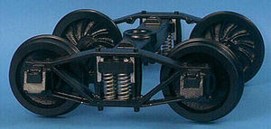
Cannonball Archbar Truck used on Minnie tender
Exploded drawing of Cannonball Ltd archbar trucks.


Tender Truck Sideframes
I started on the trucks with the cleanup and filling of the truck frames. I clamped a casting in my trusty WorkMate, and started filling (Figure 1). I've never filed cast aluminum before and quickly discovered the difference between it and steel! The file loaded up with globs of the soft aluminum at intervals between one and "X" strokes! After consulting the Live Steam E-mail forum I'm on, the following solutions were recommended: Coat the file with motor oil or Kerosene, use chalk as a lubricant, and clean the file with a file card. As I do not wish to get petroleum products on my "woodworking" WorkMate, I tried the chalk and card file route. I tried blackboard chalk, but most of it fell off with the first stroke. So I applied a very light coat of oil then applied the chalk. This worked a little better, but frequent use of the file card is needed. I understand that the type of chalk used for chalk lines sticks better, but I did not want to get blue chalk dust everywhere in my shop. Do not use the RED variety, it is a permanent type that will stay on whatever it contacts. I could not find any of the white type.
I found the file card at Sears in the tool department. It is a block of wood with one side covered with steel bristles, like a wire brush, but with the bristles bent on the ends. You run this over the file, pulling it. So the wires travel in the direction the tips point toward. Use a fair amount of pressure.
This initial filing was to remove the parting line flash, and enough of the pattern draft to make the "bars" look like flat bar. I did not file them dead flat, as the more material left the stronger the final piece.

Truck Wheels
The cast iron wheels have a very tough skin that I would recommend using carbide tool bits on. Even with carbide I reserved one for the initial cutting and used a second bit for the finishing cuts. Also a 5 inch three jaw chuck is the minimum required to hold the wheel during the initial machining. The jaws on a 4 inch chuck might hold a wheel, but the jaws would be only minimally engaged with the scroll. This might over strain either the jaw threads or the scroll itself.
Cannonball recommends three different ways to mount the finished wheel to the axle:
- Press fit between the axle and the wheel hub hole.
- A non press fit using Loctite to secure the joint.
- Two setscrews 90 degrees apart with matching flats on the axle.
With any of the above a consistent hole size in the wheel means that the axles can be turned to the same diameter not individually tailored to match a particular wheel. To insure a consistent axle hole in the wheels, I used a 9/16ths inch reamer for the final cut. For now I plan to go with the press fit option for six of the wheels, with two of the wheels held by Loctite, one each, on the axles that the water pump sprockets will go.

A wheel was placed in the 3 jaw chuck with the front face against the jaws. I then used a carbide AL4 bit (left bit in Figure 13) and trued up the circumference of the flange area taking a cut about 0.010" deeper than the lowest spot on the back of the wheel at about 200 rpm (in backgear), using the bit I had designated for the roughing operation. By under cutting the skin on the flange edge first I was able to eliminate the interrupted cut that occurred at the start of each facing operation without doing this. This interrupted cut was caused, of course, by the slightly out of round edge of the casting. By taking a deep enough cut to get below the lowest spot the truing operation cut without an interrupted cut. With this edge trued up the facing operations that followed started on a machined surface, not a rough casting surface.
With the outer circumference machined I next a facing cut about 0.010" deeper than the lowest spot on the back of the wheel. Starting at about 200 rpm (in backgear), using the same roughing bit. When I had cut about halfway across I stopped the lathe and set the speed at the next higher setting, about 300 rpm. After the first cut had removed the skin, I exchanged the first bit for the one reserved for the finishing cuts. I then continued facing the back (at 300 rpm) with 0.015" to 0.020" cuts until the total thickness of the wheel was a little under 0.880".
Next I center drilled the back of the wheel, for the start of the axle hole with a #5 centerdrill at about 400 rpm. I followed this with a 7/32 inch drill for a pilot hole. I then step drilled the hole with a 1/2 inch and 17/32 inch drills. Then with the lathe in the lowest backgear speed (28 rpm on mine), I brought the hole to size with the 9/16ths reamer, held in the tailstock drill chuck. I finished by using a D4 bit (right bit in Figure 13) to debur and chamfer the opening to the hole. The burrs on the edges of the flange area were smoothed with a file. The edge away from the chuck was smoothed with the lathe running (about 300 RPM), and the other with the wheel turned by hand. The hand rotation was done because that edge was to close to the jaws to safely run the lathe under power.
Next the wheel was chucked in the 3 jaw with the machined back against the jaws. The front of the wheel was then faced to bring the total thickness down to 0.800". The Cannonball drawing shows a range of between 0.812" and 0.750". I left the wheels on the "fat" side in case I make a mistake later, and need a little metal left to correct it. The axle hole edge was chamfered and the inner and outer edges of the wheel face smoothed with the file (under power).
This was repeated for the other 7 wheel castings.
The Wheel Arbors section describes the fabrication of arbors for the Tender, Trailing Truck, Pilot Truck, and Drivers.
The next step was to clamp a wheel to a stub arbor and rough turn the tread area, then using a form tool finish turn the flange. Finally the tread area is coned to the 3 degree angle. After getting advice from several fellow model railroaders I decided to do all the machining operations on the wheels before installing them on the axles.
Alternately you could rough turn the wheels. Then after the wheels are in place on the axle the wheels are finish turned with the axle held between centers.
As the Wheel Arbor holds each wheel concentrically, the wheels were exchanged in turn until each operation was completed for all the wheels. Then the next machining operation was performed in the same manner.

The first operation is to turn the tread area of the wheel. In this case I turned the wheels all the way down to the 4.125 (4 1/8") dimension, but not all the way over to the beginning of the inner flange radius. This area will be removed when the coning operation is completed, so this is really still a rough turning operation.
Each wheel for all operations was mounted with the back of the wheel facing the headstock. The wheels can vary slightly in overall width, but the flange must be machined in a fixed relationship to the wheel back, in order for proper tracking on the rails. Mounting the wheels in the above manner insures that the above relationship will be assured for all the wheels, if the proper stops are setup during the machining. The flange tool that will be used for the final cutting also assumes this mounting orientation.

The first step in turning the tread is to set up a fixed carriage stop for the locating the point between the tread and the first rough cut for flange (Point "A" in Figure 12). With this stop in place only the final diameter of the tread has to be watched during machining. The bottom of the way is protected by a piece of craft (or popsicle) stick. While the first wheel was machined I found that the chips built up quickly between the stop and the carriage and were difficult to remove due to the limited space. So I changed the setup to that shown in Figure 14 (again with a craft stick used to protect the way). With this setup almost all (or frequently all) the chips fell away from the edge of the block, requiring only the occasional clearing of the chips.
With the stop set the first wheel was turned to the desired diameter measuring carefully for the last cut. With this final cut finished the crossfeed dial was set to 0 (zero). The rest of the wheels were then turned with the final cut done at the zero setting, rather than measured. Doing the final cut this way requires that the toolbit always be the same size (no wear allowed). The skin on the cast iron wheels is quite tough and chewed up a HSS bit almost immediately, so all the following operations (until noted later), were done using an indexable carbide toolbit and holder. This bit showed no appreciable wear, and if it had, going to a new cutting edge does not require resetting the zero point and stop location.

Figure 15 shows the tread cutting operation in progress. You will note that the bit is being fed in with a left-hand bit parallel to the lathe axis. With the triangular bit this cut the part from under the skin (as is recommended practice), reducing greatly the wear and cutting force required. With the above setup the skin is mostly broken away from behind rather than cut through.
After the final diameter was reached the tool bit was cranked out to cut the "vertical" edge, again removing any skin from below and establishing a fixed point "A" for all the wheels.
The next operation is to cut an angled face in preparation for roughing in the flange to tread fillet. With this cut all the cast iron skin should be removed, allowing a HSS tool to be used to cut the rough fillet.

For this cut I used a right-hand bit, once again run in point first. The topslide was set over 30 degrees clockwise to produce the 60 angle desired (Figure 17). While there is probably some well accepted method for locating the tool to end up at the final cutting point, I do not know it. For these cuts I locked the carriage and used only the cross and topslide feeds. To get the proper settings I carefully cut the first wheel and when I finished the cuts and the point of the tool was sitting at point "A", I zeroed the crossfeed and topslide dials.

To make the cuts the cross slide was advanced and then the tool bit run in until it broke out at the end of the cut. As the last few cuts were made I took care not to run the topslide past the zero mark. When the carriage dial reached zero the last cut was being made. Figure 18 shows a wheel after the final cut was finished.
Locomotive Frame
Minnie's frame differs from the "standard" construction methods traditional to the Live Steam hobby. The two traditional 1 1/2 inch scale methods (at least for American prototypes) are to either mill the frame from 1/2 inch steel flat stock, or to build the frame from sections of barstock. The frame from flatstock requires that you either have a decent size milling machine, a good supply of endmills, and several days of time, or that you have $100 or more to have them cut for you. The barstock method does not need a milling machine (though one helps tremendously), but does involve many precise cuts and accurate drilling to many pieces of barstock. In either case you still need to mill the journal boxes.
The major components of Minnie's frame on the other hand requires no more complex a machine than a drill press! Even this could be dispensed with a by talented person with a hand drill. I fall under the drill press standards, though. The frame consists of a sandwich of two punched 1/8 inch thick steel plates, with 1/4 inch barstock between them. All the required openings and (pilot) holes for all the bolts are already punched in the 1/8 inch plates on a CNC punch press! All that the builder needs to do to produce a strong square frame is drilling, countersinking (for flat head screws), taping, and noncritical trimming of the barstock! The bearing retainers for the axle bearings and the front axle equalizer are also assembled from punched plates. Additionally the crosspiece and outer bearing plates for the front equalizer assembly are jig welded before delivery! The accuracy of the frame comes from the accuracy of the CNC punching, and makes it much easier for the first time (or tenth time) builder.
The total time for me to assemble the first frame side was 6 hours, start to finish! I did not trim the barstock to final size, but that was because I do not yet have the full set of drawings. I left the trimming until I am sure I'm not cutting off something I may need later!
Some precautions do need to be taken before construction begins. The punching process can cause some warpage. To account for this the plates are punched in pairs. By matching the pairs, any warpage will be canceled out. Therefore I compared the plates and selected and marked each one as to its final position in the assembled frame. The pairs were matched so that they looked like Figure 1 from the top. When these are bolted together the bowing in each piece will be canceled out. I did not want them to look like Figure 2. As the warpage there would be reinforced by the plates when bolted together!.


The other precaution is that one plate be selected as an inner and one as an outer (with respect to their position in the completed frame). Both inner pieces are tapped for the assembly bolts and the outer plates are clearance drilled and countersunk for the bolts. Mixing them up or drilling out where taping is required could ruin your day! Also I had to be sure that I built both "Left hand" and "Right hand" frame sides! I marked the four plates with a permanent felt tip marker (easily removed with acetone before painting) and started construction.
The barstock was rough cut (with a torch) to length at delivery, leaving the ends rough and lumpy. The bars most all nest closely together so my first task was to cut off the very ends and file off any burrs. The bars were left overly long and the final trimming left until all the holes were drilled and the frame sides trial assembled. This allows you some room for error (front to back) in clamping the bars during the match drilling process.
The bars are drilled for all the assembly and mounting bolts by clamping them in place and drilling them using the punched pilot holes in a plate as a guide. As the inner plates need to have some of the pilot holes left as punched for tapping, I used an outer plate as a guide. The barstock for one side was drilled at a time using the outer plate that they would end up being assembled with. Using the permanent marker I marked the bars on the side that faced the outer plate. This prevented me from both mixing them up side to side and from assembling they flipped 180 degrees. The pilot holes punched in the plates are a #21, the size for a 10-32 tap. The holes in the bars are first drilled through with this size drill and then later they and the plates are drilled for clearance with a #7 drill, except for those holes in the inner plate that are to be left as is for tapping.
I started with positioning and drilling the upper 1/4 inch by 3/4 inch bar, under the assumption that the top of the frame was a more critical reference surface than the bottom for attaching locomotive components. If the edge of the bottom bar was not quite even with the bottom of the frame, less locomotive assembly problems would occur further down the line.
I also added an intermediate step to drilling the bars. I could not just clamp the bar in place and then drill all the holes for it on the drill press. The clamps had to be move frequently to clear the table as drilling progressed. This would bring in the possibility that the bar could shift as the clamps were moved throwing later holes out of alignment. Four of the five bars have holes where flat head screws will be installed. For each bar rather than drilling through all the holes, I first drilled the location of one of these screws (as close to one end as I could get) with the #21 drill, removed the bar and tapped it. The plate was drilled for clearance and a less than full depth countersink was cut. Using a 3/8 10-32 flathead screw the plate and bar were attached. The matching conic surfaces of the screw head and countersink now held the bar in general alignment and all I had to worry about was that it did not rotate around the screw as I moved the clamps.
After the first hole was drilled in the top bar, the rest of the holes in the top bar were drilled using a machinist square to insure that the top of the plate and the top of the bar lined up during clamping. I left the far end clamped as long as possible, then inserted a spare #21 drill to hold the bar in place while shifting this clamp. I would like to mention that care be taken that this spare drill not be positioned over an opening in the table, where for instance it might fall through and inconveniently roll under another piece of equipment. I then tapped and countersunk another flat head screw location at the opposite end from the first to hold the bar in place. This gave a reference surface for positioning the next bar and so on. Again where possible I installed one flat head screw in each bar first, before drilling the rest. One bar does not have any flat head screw locations, but it only has two holes so I used the spare drill in the first hole while drilling the second. Each bar was left in place as a reference to the next and burrs raised by the drilling were cleaned up before continuing. to the next bar.
I used two barclamps to hold the assembly down on the drill press table as each hole was drilled. They were quicker to position and tighten than the small C clamps used to hold the bars in position with the stamped plate. Being bigger they also had a wider throat, giving a better range of clamping positions as the assembly was moved about for drilling. The other advantage they had was that they could be initially closed and tightened with one hand, while the workpiece was held in the other, Not easy with a large C clamp. Removal was even quicker, loosen the screw, let go of it, and the bottom jaw slides down the bar.
After all the #21 holes were drilled the pieces were disassembled and the #7 clearance holes were drilled in the outer plate and bars, including those previously taped in the bars. All the holes in the bars and the outer plate are drilled for clearance, only the inner plate has tapped locations.
All the flat head screw locations on the outer plate were countersunk next. To make this easier I first carefully cut one of the previous shallow countersink holes until the screw head fit flush. With this as a reference, I lowered the table and extended the quill as far down as it would go. The table was then raised until the countersink bit seated in the just cut countersink hole then locked the table in place. Now all that had to be done to cut the rest to the correct depth was to move the plate and cut until the quill bottomed. Each countersink cut was uniform and the proper depth without having to check each one. I used cutting oil during all the countersinking, to both speed the rate of cut and save the cutting edges of the countersink bit. Any remaining burrs were once again removed.
Next the inner plate was tapped and drilled for clearance as required, then the burrs removed. All the pieces were then reassembled and except for trimming the bars later, that side of the frame was finished! The present I am wearing a brace on my "Good" wrist because of Carpal Tunnel problems, and even with this hindrance it took only six hours to complete the one side of the frame.
The other frame side was finished in the same manner. Then the pieces were disassembled, the 1/4 barstock trimmed to length, and the frames sides reassembled to check for proper fit.
Video
<videoflash>xZ3aow8QRvg</videoflash>
<videoflash>wYhdnZqN_lM</videoflash>