Balanced Air Brakes from Scratch: Difference between revisions
| Line 69: | Line 69: | ||
<gallery widths="300px" heights="300px"> | <gallery widths="300px" heights="300px"> | ||
File:CabooseTruck BrakePadMaterial.jpg|Brake pad material from McMaster-Carr. | File:CabooseTruck BrakePadMaterial.jpg|Brake pad material from McMaster-Carr. | ||
File:CabooseTrucks AttachingBrakeShoes.jpg|The Brake Pads are cut and glued to the aluminum Brake Shoes with JB Weld. The Brake Shafts are pulled tight using rebar ties attached to the axle. This holds the shoes tightly to the pads and forms the curve in the shoes. | |||
</gallery> | </gallery> | ||
Revision as of 00:18, 28 October 2015
Fall 2015
During the summer of 2015 I began studying air brakes and how live steam modelers incorporate working air brake systems on their trains. I was well into building a Kitsap Live Steamers caboose kit and decided to add a fully operational balanced air brake system to the caboose.
This is my first attempt at building operating air brakes, and I am quite pleased with the results. Air brakes will certainly be added to my other equipment.
Equipment

- Clippard parts:
- UDR-17-1 : Stainless steel double-acting cylinder, 1 inch stroke, 1-1/16 inch bore, 5/16 inch shaft
- CT4 : #10-32 to 1/8” ID Hose Connector, designed for Clippard's Polyurethane hose
- T44-4 : Tee fitting, 1/8 inch ID
- URH1-0804-BKS : Urethane tube 1/8 inch ID
- TV-3SP : 3-Way Toggle Valve, ENP Steel Toggle, 1/8" NPT
- MCV-2 : Check Valve, #10-32 Ports
- 15090-1 : 1/8” NPT to #10-32 “L” Fitting
Tools and Supplies
Build Gallery
Air Tank
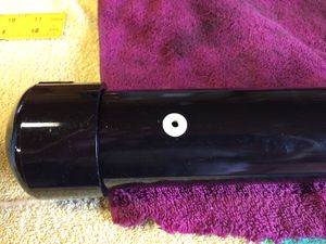
I started with the air tank. It is constructed using 2 inch diameter PVC pipe (schedule 40) with a pair of caps. A hole was drilled and tapped for 10-32 threads to accept a Clippard fitting. An adhesive dot was placed over the hole before painting.

Brake Shoes
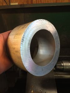
In an effort to save money I decided to cut brakes from a ring of aluminum purchased from McMaster-Carr. The pipe has a 4 inch inside diameter and a 6 inch outside diameter.
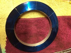
A 1/2 inch width of the aluminum pipe was parted off on the lathe. Here it has been blued and marked for cutting.


Mechanical Drawings
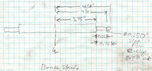
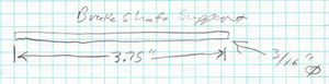
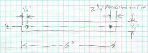
Brake Shaft for Caboose Trucks. Two required per truck.
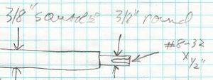
End detail of Brake Shaft. Turn ends down to 3/8 inch on lathe. Drill and tap for 8-32 threads 1/4 inch deep.
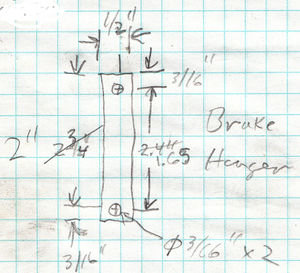
Brake Hanger, four required per truck.
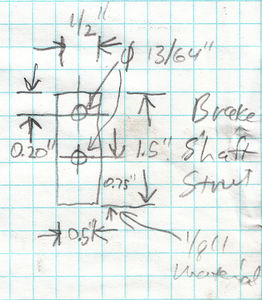
Brake shaft strut, two required per Brake Shaft.
Short lever to be inserted between struts, one per truck required.
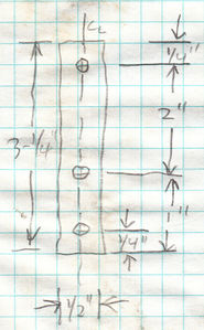
Long lever, inserted between struts and connected to Bolster Fulcrum, one required per truck.
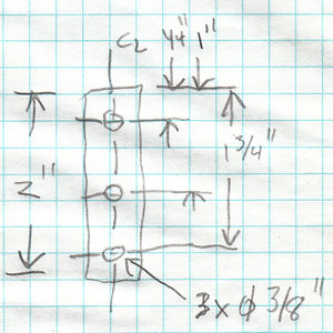
Brake Shaft Support, two required per Brake Shaft. Later I started cutting one 7 inch long support. After inserting and welding onto the struts the rods are bent and welded to the ends of the Brake Shaft.
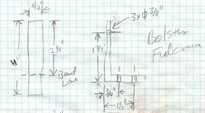
The Bolster Fulcrum is attached to the side of the bolster.
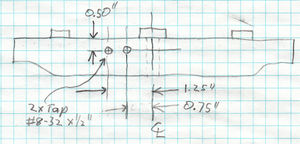
Location of tapped holes for the Bolster Fulcrum.
Connecting lever runs underneath the truck and connects the long and short levers.
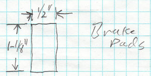
Brake pads, four required per truck.


Assembling Brake Shafts
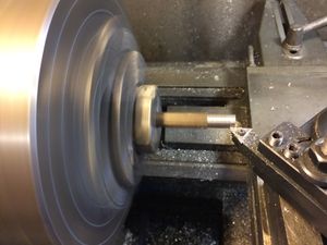
Turning one end of a Brake Shaft.
File:CabooseBrakes TestFit.jpg
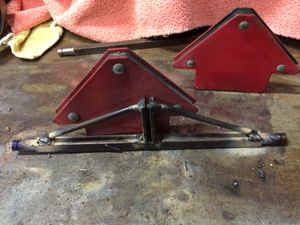
The two Brake Struts were welded onto the Brake Shaft. Then the 7 inch long Support Shaft was inserted into the holes at the end of the Brake Struts, bent down at the ends, and welded at the ends as well as at the Brake Struts.
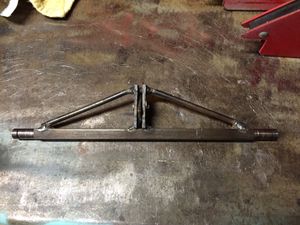
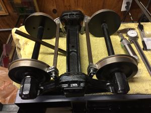
The Brake Shaft assembly is cleaned after welding. Note that a temporary lever has been inserted and pinned between the two Brake Shaft Struts to help hold the gap during welding.
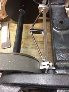
Test fit of assembled Brake Shaft in truck.


Brake Pads
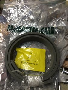
Brake pad material from McMaster-Carr.
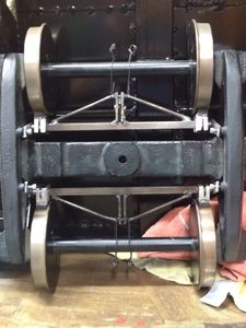
The Brake Pads are cut and glued to the aluminum Brake Shoes with JB Weld. The Brake Shafts are pulled tight using rebar ties attached to the axle. This holds the shoes tightly to the pads and forms the curve in the shoes.

