Balanced Air Brakes from Scratch: Difference between revisions
Jump to navigation
Jump to search
No edit summary |
|||
| Line 25: | Line 25: | ||
== Build Gallery == | == Build Gallery == | ||
=== Air Tank === | |||
<gallery widths="300px" heights="300px"> | <gallery widths="300px" heights="300px"> | ||
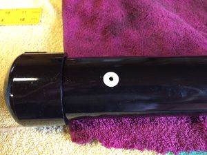
File:FreightTruckAirBrakes1.jpg|I started with the air tank. It is constructed using 2 inch diameter PVC pipe (schedule 40) with a pair of caps. A hole was drilled and tapped for 10-32 threads to accept a Clippard fitting. An adhesive dot was placed over the hole before painting. | File:FreightTruckAirBrakes1.jpg|I started with the air tank. It is constructed using 2 inch diameter PVC pipe (schedule 40) with a pair of caps. A hole was drilled and tapped for 10-32 threads to accept a Clippard fitting. An adhesive dot was placed over the hole before painting. | ||
</gallery> | |||
=== Brake Shoes === | |||
<gallery widths="300px" heights="300px"> | |||
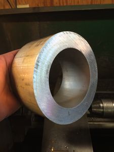
File:FreightTruckAirBrakes4.jpg|In an effort to save money I decided to cut brakes from a ring of aluminum purchased from [http://www.mcmaster.com McMaster-Carr]. The pipe has a 4 inch inside diameter and a 6 inch outside diameter. | File:FreightTruckAirBrakes4.jpg|In an effort to save money I decided to cut brakes from a ring of aluminum purchased from [http://www.mcmaster.com McMaster-Carr]. The pipe has a 4 inch inside diameter and a 6 inch outside diameter. | ||
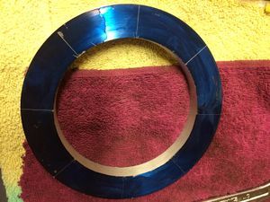
File:FreightTruckAirBrakes5.jpg|A 1/2 inch width of the aluminum pipe was parted off on the lathe. Here it has been [https://en.wikipedia.org/wiki/Marking_blue blued] and marked for cutting. | File:FreightTruckAirBrakes5.jpg|A 1/2 inch width of the aluminum pipe was parted off on the lathe. Here it has been [https://en.wikipedia.org/wiki/Marking_blue blued] and marked for cutting. | ||
</gallery> | |||
=== Mechanical Drawings === | |||
<gallery widths="300px" heights="300px"> | |||
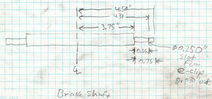
File:CabooseBrakes BrakeShaft.jpg|Brake Shaft for Caboose Trucks. Two required per truck. | |||
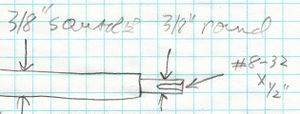
File:CabooseBrakes BrakeShaftDetail.jpg|End detail of Brake Shaft. Turn ends down to 3/8 inch on lathe. Drill and tap for 8-32 threads 1/4 inch deep. | |||
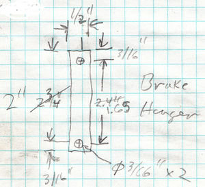
File:CabooseBrakes BrakeHanger.jpg|Brake Hanger, four required per truck. | |||
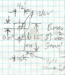
File:CabooseBrakes BrakeShaftStrut.jpg|Brake shaft strut, two required per Brake Shaft. | |||
</gallery> | </gallery> | ||
Revision as of 23:13, 27 October 2015
Fall 2015
During the summer of 2015 I began studying air brakes and how live steam modelers incorporate working air brake systems on their trains. I was well into building a Kitsap Live Steamers caboose kit and decided to add a fully operational balanced air brake system to the caboose.
This is my first attempt at building operating air brakes, and I am quite pleased with the results. Air brakes will certainly be added to my other equipment.
Equipment

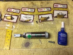
Here is a spread of Clippard parts used for the balanced air brake system.
- Clippard parts:
- UDR-17-1 : Stainless steel double-acting cylinder, 1 inch stroke, 1-1/16 inch bore, 5/16 inch shaft
- CT4 : #10-32 to 1/8” ID Hose Connector, designed for Clippard's Polyurethane hose
- T44-4 : Tee fitting, 1/8 inch ID
- URH1-0804-BKS : Urethane tube 1/8 inch ID
- TV-3SP : 3-Way Toggle Valve, ENP Steel Toggle, 1/8" NPT
- MCV-2 : Check Valve, #10-32 Ports
- 15090-1 : 1/8” NPT to #10-32 “L” Fitting
Tools and Supplies
Build Gallery
Air Tank
Brake Shoes
In an effort to save money I decided to cut brakes from a ring of aluminum purchased from McMaster-Carr. The pipe has a 4 inch inside diameter and a 6 inch outside diameter.
A 1/2 inch width of the aluminum pipe was parted off on the lathe. Here it has been blued and marked for cutting.
