Adventures of 486: Difference between revisions
| Line 59: | Line 59: | ||
File:2014-03-19 21.22.30.jpg|Here I am preparing to press the wheel onto the axle. Notice that the bearings are already on the axle! | File:2014-03-19 21.22.30.jpg|Here I am preparing to press the wheel onto the axle. Notice that the bearings are already on the axle! | ||
File:2014-03-19 21.26.46.jpg|The wheel gauge shows the back-to-back dimension is correct, per IBLS Wheel Standard. | File:2014-03-19 21.26.46.jpg|The wheel gauge shows the back-to-back dimension is correct, per IBLS Wheel Standard. | ||
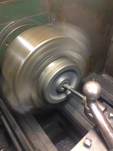
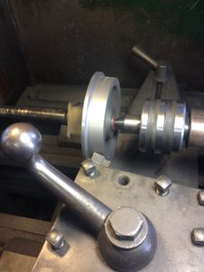
File:2014-03-29 14.54.22.jpg|Machining the tread and flange of the new wheel. I know this is not the best setup. Typically you would machine "between centers"; a live center in the tailstock and a dead center in the headstock. I don't have a "dog" that will transfer motion to the axle, so I am using the 4-jaw chuck. The TIR (Total Indicated Readout) is adjusted to less than 0.0005 inches off of the bearing surace of the axle. | |||
File:2014-03-29 15.00.57.jpg|I use my dial calipers as a poor man's DRO (digital readout). I take an initial measurement with the dial calipers. With each cut I decrease the dial calipers by that amount. I continue taking 20 mil (0.020 inches) cuts across the tread until I am withing 40 mils of the final measurement. Then I stop the lathe and take a measurement, and slowly "sneak up" on the final measurement, taking 10 or even 5 mil cuts. | |||
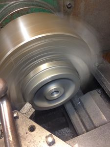
File:2014-03-29 16.33.08.jpg|This is the final cut across the tread, taking the last 5 mils off. This is at an angle of 2-5/6 degrees per IBLS spec. The final tread diameter is 4.000 inch its widest point next to the flange. Most cuts were performed at 1600 rpm. Slowed to 300 rpm on final cuts. | |||
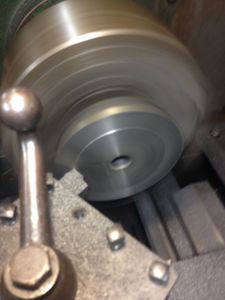
File:2014-03-29 16.41.11.jpg|What kind of cutter is this? Here is a trick l learned from an experienced machinist. The surplus store where I purchase tools did not have a cutting tool with the proper diameter for the flanges. The machinist said "you have to improvise with what you have", and suggested I use a corner milling bit with the correct diameter. Sure enough it works great! The final cuts of the tread and the shaping of the flange were done at 300 rpm. | |||
</gallery> | </gallery> | ||
Revision as of 23:35, 30 March 2014
by Daris A Nevil
IBLS Webmaster
In this column we'll following the adventures of Allen Mogul #486.
Bagley Oil Burner
Replaced the Peterson oil burner with a Bagley Oil Burner.
Toolbox of Requirement
Everything that is is needed for #486 is in the Toolbox of Requirement.
Repairs
A derailment due to a branch across the rails damaged the pony truck described here: Allen Mogul Pony Pivot Repair.
Pony Wheel Damage
14 March 2014
I'm pretty hard on my Allen Mogul #486. Seems like every time I take it out to a meet I break something.
The most recent damage occurred happened at Houston Area Live Steamers Chugga Chugga Chili fest. We had a great meet, enjoyed some hot chili, and drove trains all day.
During a run #486 hopped off the rails at a turnout. It went half way onto the wrong turn. Took a bit of work for me and my passenger, Spence, to get it lined back up on the rails.
I didn't take time to inspect for damage. Everything seemed fine, so I continued to run throughout the meet. At one point I heard a squeaking noise up front, but again I ignored the warning sign.
I didn't discover what was wrong until I loaded up after the meet. What I discovered is shown below. During the derailment the cattle guard caught the frog or one of the guard rails and was bent back about 3/8". The brace between the apron and the cattle guard was bent down and started rubbing against the flange of the pony wheel.
By the time I loaded up the flange had been worn to a fine edge. Looks like I will have to turn a new wheel.
But hey, that's part of the fun of the hobby too!
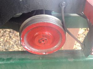
The flange of the wheel on Allen Mogul #486 was ground down by the bent brace.
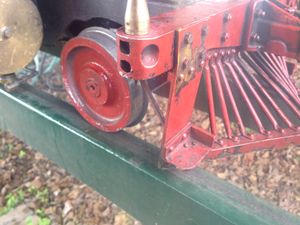
This photo shows the cattle guard bent from a derailment. This caused a brace to curve down onto the flange of the pony truck.


This evening I began work on the damage to #486. My first try thought was "I bet I can hammer the cattle guard straight with a rubber mallet.". Well, after a few whacks I decided that was not going to work out.
Removed the cattle guard and used my 30 ton press to straighten out the kinks. The engineer's side brace was bent, along with the bottom of the guard. A few well placed pressure points straightened it right up! Looks as good as new (except for the paint).
The point of the guard was cracked. It had been brazed when it was made. I don't have brazing equipment, but I do have a Lincoln AC225 welder. I used a small rod, set the current to 70 amps, and welded the joint from underneath. I'm not a professional welder, but it turned out ok. It should be strong. 70 amps was a little too high; it melted part of the edge of the brace. I should have used 60 amps. or even 40 amps. But, the weld will hold, and I think it will look fine after it is painted.
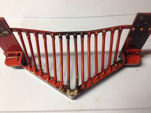
Cattle guard for Allen Mogul #486 after straightening and welding.
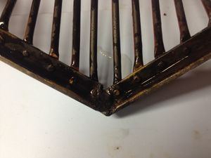
Back side of cattle guard of Allen Mogul #486 shows weld repair at point seam.
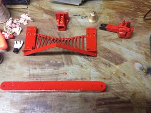
First coat of paint on the cow catcher and associated parts.
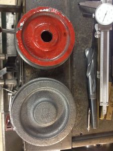
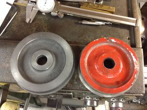
Here is the worn wheel and the new blank, part number M300. I found out from Marty Knox that the M199 and M300 are the same casting. After I got off the phone, I saw the note on their price list that says the same. Duh!
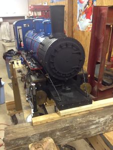
Number 486 temporarily "jacked up" on locomotive stand while repairs are underway.
The wheel casting is mounted in the four jaw chuck. First operation is to center drill.
Next operation: drill with 45/64 inch drill bit (not shown). I measured the size of the axle that the wheel would be pressed onto, and it was 0.751 inches. So I bored the hole to 0.749 for a tight fit (shown here).
Made 4 facing cut passes taking 0.020 inches off each pass.
Turned the wheel around in the chuck, and made sure the front face was firmly pressed against the chuck face. Then made several face cuts of 0.020 inches each until the wheel was 0.8125 inches thick, per the Allen drawing.
Here is the bored and faced wheel compared to the worn wheel. I will press the new wheel onto the axle, then cut the tread. This will assure that the tread is cut concentric with the axle.
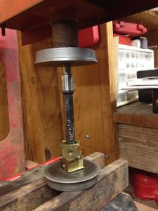
Here I am preparing to press the wheel onto the axle. Notice that the bearings are already on the axle!
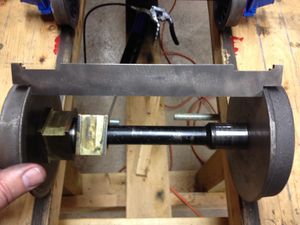
The wheel gauge shows the back-to-back dimension is correct, per IBLS Wheel Standard.
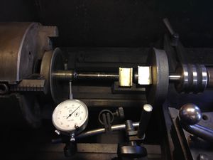
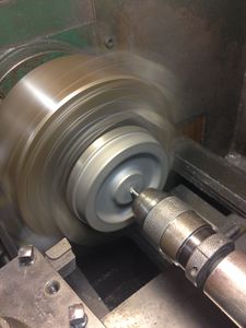
Machining the tread and flange of the new wheel. I know this is not the best setup. Typically you would machine "between centers"; a live center in the tailstock and a dead center in the headstock. I don't have a "dog" that will transfer motion to the axle, so I am using the 4-jaw chuck. The TIR (Total Indicated Readout) is adjusted to less than 0.0005 inches off of the bearing surace of the axle.
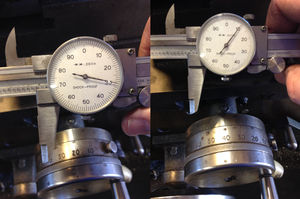
I use my dial calipers as a poor man's DRO (digital readout). I take an initial measurement with the dial calipers. With each cut I decrease the dial calipers by that amount. I continue taking 20 mil (0.020 inches) cuts across the tread until I am withing 40 mils of the final measurement. Then I stop the lathe and take a measurement, and slowly "sneak up" on the final measurement, taking 10 or even 5 mil cuts.
This is the final cut across the tread, taking the last 5 mils off. This is at an angle of 2-5/6 degrees per IBLS spec. The final tread diameter is 4.000 inch its widest point next to the flange. Most cuts were performed at 1600 rpm. Slowed to 300 rpm on final cuts.
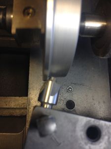
What kind of cutter is this? Here is a trick l learned from an experienced machinist. The surplus store where I purchase tools did not have a cutting tool with the proper diameter for the flanges. The machinist said "you have to improvise with what you have", and suggested I use a corner milling bit with the correct diameter. Sure enough it works great! The final cuts of the tread and the shaping of the flange were done at 300 rpm.


