LBSC's Virginia: Difference between revisions
| Line 66: | Line 66: | ||
I finally narrowed things down to the center to center lengths of the eccentric rods. LBSC has his eccentric rod center-to-center lengths (from expansion link to the wheel axle) at 3-7/16 inches. The expansion link however has the eccentric connection holes on a radius of 3.5 inches to the wheel axle. That steenth of an inch (a shorter way to say sixteenth of an inch) is what was giving me all the problems. I am not sure if this would or would not cause any problems in the real world especially since there are other adjustments that could be made to try and compensate for this. SolidWorks however did alert me I think to what was a potential binding problem with the valve train linkage geometry. I am now fully defined and ready to start on the boiler. | I finally narrowed things down to the center to center lengths of the eccentric rods. LBSC has his eccentric rod center-to-center lengths (from expansion link to the wheel axle) at 3-7/16 inches. The expansion link however has the eccentric connection holes on a radius of 3.5 inches to the wheel axle. That steenth of an inch (a shorter way to say sixteenth of an inch) is what was giving me all the problems. I am not sure if this would or would not cause any problems in the real world especially since there are other adjustments that could be made to try and compensate for this. SolidWorks however did alert me I think to what was a potential binding problem with the valve train linkage geometry. I am now fully defined and ready to start on the boiler. | ||
I forgot to mention that I had to make the Reversing Arm 3/8" longer so that the Reach Rod from the Johnson Bar would not hit wheel with the Johnson Bar in full forward position. | |||
=== May 12, 2014 === | |||
Guess what I ran across while starting to read about the boiler? You got it, an addendum for the reversing lever. LBSC ran across the same problem I encountered with it. His fix is to attach the offending sector support in a horizontal position to the boiler above the suspension. Since my goal is to adhere to his design as close as possible I will have to redesign my redesign, so to speak. LOL. This should only effect the rear of the frame that I extended and the reach rod, should be an easy fix. | |||
== Gallery of Models == | == Gallery of Models == | ||
Revision as of 21:17, 14 May 2014
Modeling LBSC's Virginia in SolidWorks
by Don Althouse
April 14, 2014
I have been attempting to make an electronic solid model of LBSC's Virginia from an article in Model Engineer written in 1956. This is by far one of the most complex and, shall I say, a bit hard to understand at times, projects I have found on the Internet to model.
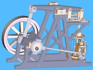
I am a mechanical designer engineer that loves to work with SolidWorks (my design program) and have been working on this model since about the middle of February 2014. I was starting to model the mechanical lubricator and in doing a little research ran across the IBLS website. I thought you might enjoy seeing what I have accomplished so far, so I am attaching a JPEG picture of what I call the chassis.
Now that I have read a little more in the article, it seems my frames will have to be updated once again to accommodate the lubricator mounts and the linkage, a never ending process but one I am quite use to as I have done my fair share of drafting and design work over the years. I hope you enjoy the picture, modeling this train has kept me quite busy and for that I am very thankful.

April 16, 2014
I have several other LBSC articles as well. The TichSm, Rose, Juliet, Dot and Doris Class 5, all of which I believe are original Model Engineer articles that I have downloaded from LBSC Steam Engine Plans.
This website has been a great resource for me to get project plans to model and keep myself busy. I have modeled quite a few of the projects from this site, most of which dealt with steam, mainly different variations of steam engines, with the exception of an old CASE steam tractor model (see drawings below). I have been making these models for the past several years and was looking for something more involved when I ran across the LBSC article.
Beam engine modeled in Solid Works by Don Althouse
Twin cylinder engine modeled by Don Althouse
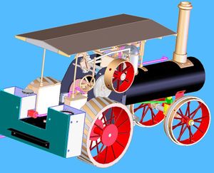
Case steam tractory modeled by Don Althouse


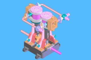
The more I get done with this LBSC model the more I am intrigued about Locomotives and the various ways they went about solving problems for various things. For instance the lubricator assembly, (not quite done and slightly modified, see attachment)what a great idea, so simple yet a very functional mechanical device, how cool!

My one concern about this endeavor is that my computer is very old as is my version of SolidWorks. I am running a 12 year old 32-bit Pentium 4 with an NVIDIA GeForce FX 5200 graphics card. Not the best system in the world for doing solid modeling. This will be by far the biggest and most complex model I have attempted to do on my system and I am not sure at this point if I will be able to get a full completed model due to lack of memory and the slow speed of my computer.
SolidWorks is a memory hog and there in lies my concern, the more I get done, the more memory is used. There are different things I can try to accomplish the task but at this point I really don't know if they will work or not, we will just have to see. I believe I can get all the sub-assemblies done though.
April 22, 2014
I finished the lubricator assembly and got the linkage for it done as well.

April 24, 2014
At this point I am writing a general outline of what I have done or should I say a general outline of the way LBSC designed a train. I have put together a PowerPoint Presentaion that I use on LinkedIn and update it when I get a few more assemblies done. I have included it in this article, below. At this point I have 175 unique parts and about 45 sub-assemblies. My intent with the presentation is to give a general outline from start to finish of the 1956 article.
May 5, 2014
As you know I ran into an issue with the Johnson Bar placement on the frame. I have contacted a friend about this and he said he would check his plans and get back to me. In the mean time I have moved on. I got the Johnson Bar modeled and updated the frame. I had to extend the rear of the frame by 1.5 inches so the Johnson Bar would not interfere with the suspension. In addition to this I also had to make an offset for the lever pin that attaches the Reach Rod to the Johnson Bar Lever so that it would not interfere with the Sector Supports. The reach Rod has also been extended by 1.5 inches.
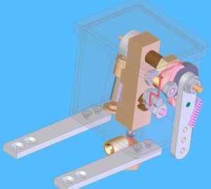
I have also updated the Mechanical Lubricator Assembly which shows the missing pawl on the top of the box.
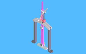
Johnson bar


May 11, 2014

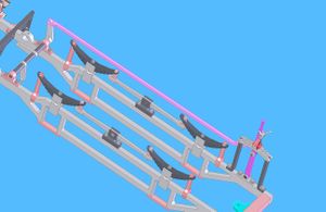
I have been playing around with the Stephenson valve gearing once again. I provided a JPEG, above, with it in place, but it never seemed to work right in SolidWorks so I decided to give it a better look and concentrate on the geometry of the whole valve train. I started my investigation by making sure that everything was in line and on center to the wheel axle, the expansion link and eccentrics to the expansion link were of particular concern. I could never get my model to be "fully defined". When I would attach a final piece, say the reversing arm to the reach rod, to connect the whole valve assembly SolidWorks would give me an error saying "over defined".
I finally narrowed things down to the center to center lengths of the eccentric rods. LBSC has his eccentric rod center-to-center lengths (from expansion link to the wheel axle) at 3-7/16 inches. The expansion link however has the eccentric connection holes on a radius of 3.5 inches to the wheel axle. That steenth of an inch (a shorter way to say sixteenth of an inch) is what was giving me all the problems. I am not sure if this would or would not cause any problems in the real world especially since there are other adjustments that could be made to try and compensate for this. SolidWorks however did alert me I think to what was a potential binding problem with the valve train linkage geometry. I am now fully defined and ready to start on the boiler.
I forgot to mention that I had to make the Reversing Arm 3/8" longer so that the Reach Rod from the Johnson Bar would not hit wheel with the Johnson Bar in full forward position.
May 12, 2014
Guess what I ran across while starting to read about the boiler? You got it, an addendum for the reversing lever. LBSC ran across the same problem I encountered with it. His fix is to attach the offending sector support in a horizontal position to the boiler above the suspension. Since my goal is to adhere to his design as close as possible I will have to redesign my redesign, so to speak. LOL. This should only effect the rear of the frame that I extended and the reach rod, should be an easy fix.
Gallery of Models
An LBSC Virginia listed on eBay, April 2014:
- A live steam, coal fired, American 4-4-0 Tender Locomotive. Built to the plans of the LBSC Virginia, likely in the 1970's and using factory castings. This is 3/4 inch scale and runs on 3-1/2 inch gauge track. The full set of large sheet original plans are include with the Engine. There is no boiler history or paperwork, it is copper, silver soldered multi-tubed type and engraved on the firebox side is, 'Q102 80lb sqi. The total length of the Locomotive and tender is 45 inches and height to the chimney is 11-3/4 inches. The usual fittings for this type, including, tender water boiler pump, axle water boiler pump, cab operated cylinder drain cocks, reverse lever, steam fed displacement oiler and tender brakes.


