Heart rocker: Difference between revisions
Jump to navigation
Jump to search
No edit summary |
|||
| Line 7: | Line 7: | ||
== Gallery == | == Gallery == | ||
<gallery widths=300px heights=300px> | <gallery widths=300px heights=300px perrow=2> | ||
File:HeartRockerDiagram BillShields.jpg|Diagram showing the four radii of a typical heart rocker, or inverted rocker. Drawing by Bill Shields. | File:HeartRockerDiagram BillShields.jpg|Diagram showing the four radii of a typical heart rocker, or inverted rocker. Drawing by Bill Shields. | ||
File:Slotted Rockers with New Base Plates - Cardo.jpg|Slotted heart rockers with new base plates. | File:Slotted Rockers with New Base Plates - Cardo.jpg|Slotted heart rockers with new base plates. | ||
File:UP Big Boy T-Truck Rocker Arr.jpg|Attached is a portion of the trailer truck arrangement drawing for a UP Big Boy. You can see the way the prototype rocker, rocker seat and bearing, and the rocker plate (which is mounted on the bottom of the frame cradle) were designed. Notice the "teeth" (or "toes") at the bottom of the rocker plate. | |||
</gallery> | </gallery> | ||
Revision as of 14:50, 31 October 2018
Alfred W. Bruce wrote in The Steam Locomotive in America:
- The inverted-rocker device was introduced about 1914. The inverted rocker was a heart-shaped rocker resting on two rolling contacts at the bottom and supporting two inclined planes at the top--one on each side of its apex center point. Thus movement in either direction produces a rolling-contact support which permits ample lateral movement with nearly any desired resistance characteristic, a quality that has retained this device in use today [approx. 1952].
Gallery
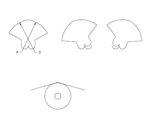
Diagram showing the four radii of a typical heart rocker, or inverted rocker. Drawing by Bill Shields.
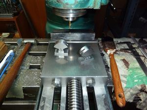
Slotted heart rockers with new base plates.
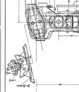
Attached is a portion of the trailer truck arrangement drawing for a UP Big Boy. You can see the way the prototype rocker, rocker seat and bearing, and the rocker plate (which is mounted on the bottom of the frame cradle) were designed. Notice the "teeth" (or "toes") at the bottom of the rocker plate.


