File:Cold Steam flow diagram.png: Difference between revisions
Jump to navigation
Jump to search
(Cold steam flow diagram. From "Model Railroader", October 1949. This schematic plan shows the path of the cold gas. The gas vaporizes from the solid dry ice in the tender. It passes through a pipe to the throttle valve in the cab and equalizing tan...) |
(No difference)
|
Latest revision as of 23:30, 5 July 2013
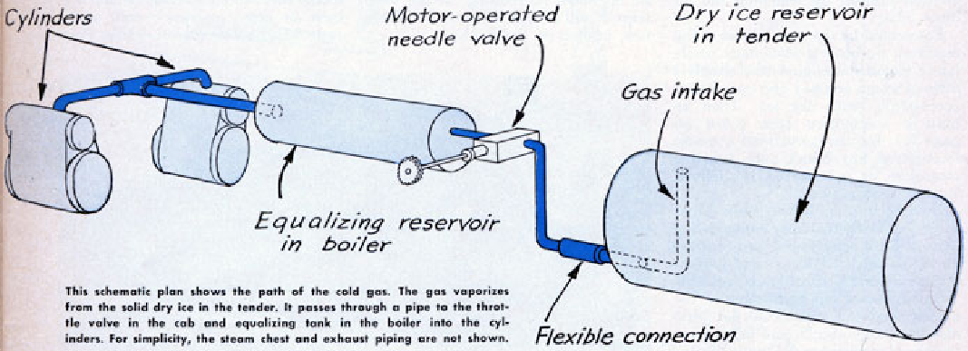
Cold steam flow diagram. From "Model Railroader", October 1949.
This schematic plan shows the path of the cold gas. The gas vaporizes from the solid dry ice in the tender. It passes through a pipe to the throttle valve in the cab and equalizing tank in the boiler into the cylinders. For simplicity, the steam chest and exhaust piping are not shown.
File history
Click on a date/time to view the file as it appeared at that time.
| Date/Time | Thumbnail | Dimensions | User | Comment | |
|---|---|---|---|---|---|
| current | 23:30, 5 July 2013 | 1,067 × 387 (401 KB) | Dnevil (talk | contribs) | Cold steam flow diagram. From "Model Railroader", October 1949. This schematic plan shows the path of the cold gas. The gas vaporizes from the solid dry ice in the tender. It passes through a pipe to the throttle valve in the cab and equalizing tan... |
You cannot overwrite this file.
File usage
The following page uses this file: