Cab Operated Cylinder Cocks: Difference between revisions
(Created page with "Category:Steam Locomotive Parts Cab Operated Cylinder Cocks Bill Van Brocklin <i>The North American Live Steamer</i>, Volume 1 Number 7, 1956 These cylinder...") |
No edit summary |
||
| Line 6: | Line 6: | ||
<i>[[The North American Live Steamer]]</i>, Volume 1 Number 7, 1956 | <i>[[The North American Live Steamer]]</i>, Volume 1 Number 7, 1956 | ||
These cylinder clocks are mechanically operated by levers and can be worked whether engine is in steam or not. They are especially userful in piston valve cylinders and when engine is standing by for long periods. Essentially they consist of a ball check, the ball held on its seat by a light spring, and a pin lifted up by an indented rod. The rod is moved by a connecting arm on each side, | [[File:VanBrocklin CylinderCocks1.jpg|thumb|right|400px]] | ||
These cylinder clocks are mechanically operated by levers and can be worked whether engine is in steam or not. They are especially userful in piston valve cylinders and when engine is standing by for long periods. Essentially they consist of a ball check, the ball held on its seat by a light spring, and a pin lifted up by an indented rod. The rod is moved by a connecting arm on each side, which are in turn moved by a cross shaft with two arms. This runs through the engine frame and one arm is extended up and moved from there by a rod to the cab. The photo will explain this much better than words. | |||
The most difficult part is lining up the slots in the body parts on the cylinders. However, the rod can be bent slightly to overcome any small error. It is important that these rods slide freely back and forth and of course move th epins up and down. The spring on the ball should not be too stiff, as its only purpose is to keep the ball from floating off its seat when too much oil is blown off. Be sure when the ball is seated there is a slight clearance between it and the pin. The 1/16 hole to cylinder should be as close to cover as possible so all trapped condensate can be blown off. The pins at the ends of the rod keep it from pulling out of the slots in cock body. These cocks were used on a 3-1/2 gauge engine. | The most difficult part is lining up the slots in the body parts on the cylinders. However, the rod can be bent slightly to overcome any small error. It is important that these rods slide freely back and forth and of course move th epins up and down. The spring on the ball should not be too stiff, as its only purpose is to keep the ball from floating off its seat when too much oil is blown off. Be sure when the ball is seated there is a slight clearance between it and the pin. The 1/16 hole to cylinder should be as close to cover as possible so all trapped condensate can be blown off. The pins at the ends of the rod keep it from pulling out of the slots in cock body. These cocks were used on a 3-1/2 gauge engine. | ||
| Line 13: | Line 15: | ||
: Pine Street | : Pine Street | ||
: Dover, Mass. | : Dover, Mass. | ||
<gallery widths="300px" heights="300px"> | |||
File:VanBrocklin CylinderCock Figure1.jpg|Figure 1: Body | |||
File:VanBrocklin CylinderCock Figure2.jpg|Figure 2: Stem | |||
File:VanBrocklin CylinderCock Figure3.jpg|Figure 3: Rod | |||
File:VanBrocklin CylinderCock Figure4.jpg|Figure 4: Spring | |||
File:VanBrocklin CylinderCock Figure5.jpg|Figure 5: Assembly | |||
</gallery> | |||
Latest revision as of 22:32, 11 May 2015
The North American Live Steamer, Volume 1 Number 7, 1956

These cylinder clocks are mechanically operated by levers and can be worked whether engine is in steam or not. They are especially userful in piston valve cylinders and when engine is standing by for long periods. Essentially they consist of a ball check, the ball held on its seat by a light spring, and a pin lifted up by an indented rod. The rod is moved by a connecting arm on each side, which are in turn moved by a cross shaft with two arms. This runs through the engine frame and one arm is extended up and moved from there by a rod to the cab. The photo will explain this much better than words.
The most difficult part is lining up the slots in the body parts on the cylinders. However, the rod can be bent slightly to overcome any small error. It is important that these rods slide freely back and forth and of course move th epins up and down. The spring on the ball should not be too stiff, as its only purpose is to keep the ball from floating off its seat when too much oil is blown off. Be sure when the ball is seated there is a slight clearance between it and the pin. The 1/16 hole to cylinder should be as close to cover as possible so all trapped condensate can be blown off. The pins at the ends of the rod keep it from pulling out of the slots in cock body. These cocks were used on a 3-1/2 gauge engine.
- W. Van Brocklin, Jr.
- Pine Street
- Dover, Mass.
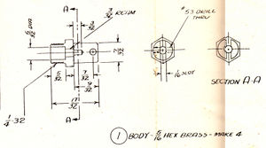
Figure 1: Body
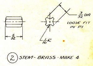
Figure 2: Stem
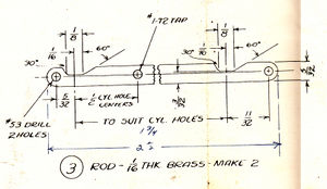
Figure 3: Rod
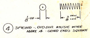
Figure 4: Spring
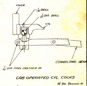
Figure 5: Assembly


