CAD: Difference between revisions
Jump to navigation
Jump to search
| Line 12: | Line 12: | ||
* [http://www.pacificlocomotive.com/process.php Process of designing spoke wheels in CAD, <i>Pacific Locomotive Works</i>] | * [http://www.pacificlocomotive.com/process.php Process of designing spoke wheels in CAD, <i>Pacific Locomotive Works</i>] | ||
<gallery widths=300px heights=300px perrow=2> | |||
File:American driver.PNG|6 inch driver for 1.5 inch scale 4-4-0 American, designed in Fusion360. | |||
File:Hudson Drivers and Rods Fusion360 model.PNG|Hudson drivers and rods, Fusion360 model | |||
</gallery> | |||
== External Links == | == External Links == | ||
Revision as of 18:47, 27 December 2019

From Wikipedia:
- Computer-aided design (CAD) is the use of computer systems to assist in the creation, modification, analysis, or optimization of a design. CAD software is used to increase the productivity of the designer, improve the quality of design, improve communications through documentation, and to create a database for manufacturing. CAD output is often in the form of electronic files for print, machining, or other manufacturing operations.
Don Althouse used SolidWorks to model LBSC's Virginia.
Designing Wheels
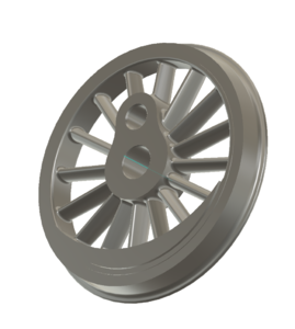
6 inch driver for 1.5 inch scale 4-4-0 American, designed in Fusion360.
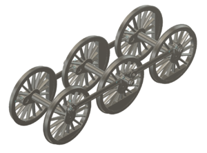
Hudson drivers and rods, Fusion360 model

