Building a Kitsap Caboose: Difference between revisions
| Line 39: | Line 39: | ||
<gallery widths="400px" heights="400px"> | <gallery widths="400px" heights="400px"> | ||
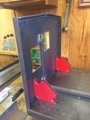
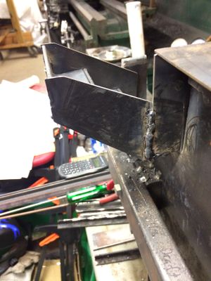
File:KitsapLiveSteamersCabooseBatteryBox.jpg|I decided to model the caboose after the Santa Fe caboose #999187 located at the [[Comanche & Indian Gap Railroad]] railroad. I needed a battery box in place of the tool cellar. Here my nephew Stephen is setting up to weld the box together. Note that this battery box was built from scratch, and is not part of the Kitsap Live Steamer's kit. | File:KitsapLiveSteamersCabooseBatteryBox.jpg|I decided to model the caboose after the Santa Fe caboose #999187 located at the [[Comanche & Indian Gap Railroad]] railroad. I needed a battery box in place of the tool cellar. Here my nephew Stephen is setting up to weld the box together. Note that this battery box was built from scratch, and is not part of the Kitsap Live Steamer's kit. | ||
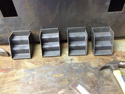
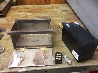
File:KitsapCabooseBatteryBox1.jpg|The battery box is large enough to hold a standard gel-cell battery. The battery will power the lights on the caboose. | File:KitsapCabooseBatteryBox1.jpg|The dimensions of the box is 6-1/2 inches deep, 4-1/2 inches deep, and 3-3/4 inches high. After installation on the chassis the box looked a bit over-sized, so you may need to adjust for your taste. The battery box is large enough to hold a standard gel-cell battery. The battery will power the lights on the caboose. The two front braces were cut from 1/2 inch square steel tubing. It is cut down to about 1/8 inch high, so that the side ribs show prominently like the prototype. | ||
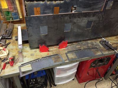
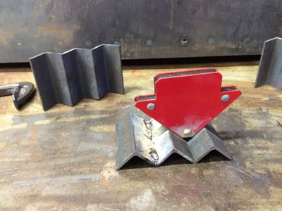
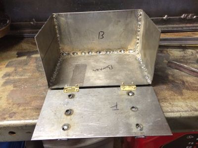
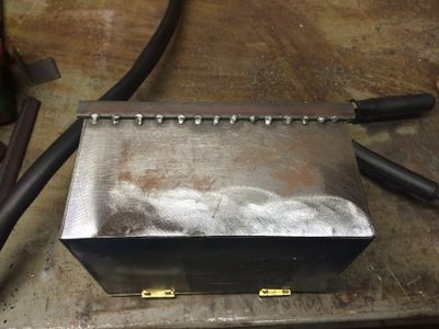
File:KitsapCabooseBatteryBox2.jpg|Here you can see the filler welds that hold the front braces onto the faceplate. Holes were drilled in the faceplate, the braces were clamped onto the faceplate, and the holes were filled with welds from the backside of the faceplate. The welds were ground down flat. | File:KitsapCabooseBatteryBox2.jpg|Here you can see the filler welds that hold the front braces onto the faceplate. Holes were drilled in the faceplate, the braces were clamped onto the faceplate, and the holes were filled with welds from the backside of the faceplate. The welds were ground down flat. | ||
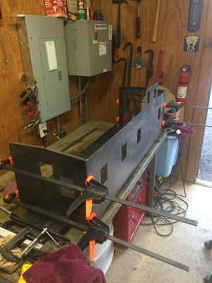
File:KitsapCabooseBatteryBox3.jpg|The box was welded together using "stitch" welds to prevent warping. | File:KitsapCabooseBatteryBox3.jpg|The box was welded together using "stitch" welds to prevent warping. | ||
| Line 45: | Line 45: | ||
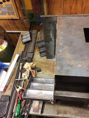
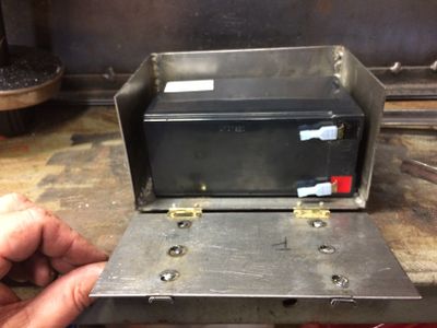
File:KitsapCabooseBatteryBox5.jpg|The front brace is welded in place. Other components shown here include the terminal strip and the fuse holder. | File:KitsapCabooseBatteryBox5.jpg|The front brace is welded in place. Other components shown here include the terminal strip and the fuse holder. | ||
File:KitsapCabooseBatteryBox6.jpg|The terminal strip and fuse holder have been mounted on the side of the battery box. I made a mistake here, in that I mounted the terminal strip on the side where the air tank will reside. Not much access room after the battery box and air tank are mounted next to each other. | File:KitsapCabooseBatteryBox6.jpg|The terminal strip and fuse holder have been mounted on the side of the battery box. I made a mistake here, in that I mounted the terminal strip on the side where the air tank will reside. Not much access room after the battery box and air tank are mounted next to each other. | ||
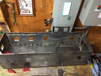
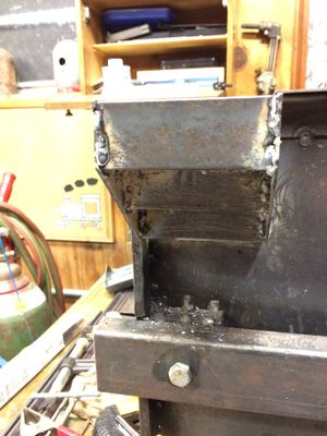
File:KitsapCabooseBatteryBox7.jpg|The battery box has been welded onto the caboose chassis. The mounting brackets are 1/2 by 1/2 inch angle steel. | |||
</gallery> | </gallery> | ||
Revision as of 19:55, 13 September 2015
Build Gallery
Frame
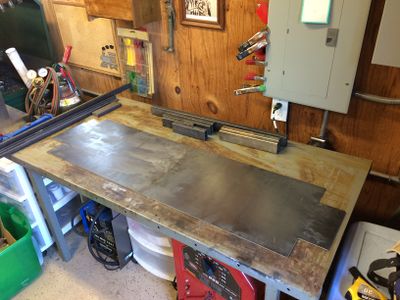
Laying out the base and other parts for the Kitsap Live Steamers caboose kit. Photo by Daris A Nevil, April 2015.
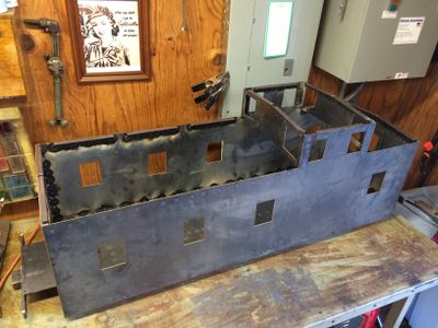
The floor plates have been welded to the side beams. The center beam and bolster supports have been attached as well. The end beam has been welded to the end of the floor and the coupler pocket. The half rounds were previously brazed on the end beam.
Top view of floor plats showing "stitch" welds.
Bottom view of the floor shows stitch welds. These welds were made using a red Lincoln "tombstone" welder (seen under the table) with 1/8 inch 6011 rods. You must be very careful to prevent warping during welding, even with this thicker material. By careful I mean make short stitch welds (1/4 inch) and allow to cool between welds (10-15 seconds). Use lots of C-clamps to hold materials tightly together during welding.
Angle iron has been stitched onto the end wall, which is now positioned for test fitting. I used small brass hinges for the doors, and brazed them to the steel. In retrospect I wish I had used rivets.
Preparing for welding the four sides together. The clamps are from Harbor Freight, and were made for wood projects, but I found they worked quite well for this project (and I already had them).
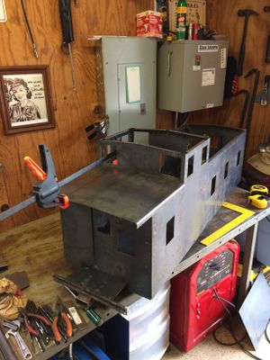
The four sides have been welded together and to the floor. Be sure to use a square to align the sides. Note the angle iron on the upper edge was welded in sections. This was a grave mistake on my part, as it causes severe warping of the sides. I later removed these and replaced with one long piece as the instructions suggest.


Body
Angle iron has been welded to the edges of the cupola front and back sections.
The cupola front and back have been welded to the cupola sides.
The short section of the roof is prepared for welding. The roof is stitch welded on the inside.
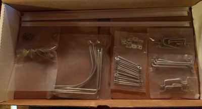
A box full of detail parts from Precision Steel Car.
The steps must be cut the same length. I trimmed all these to the same length in the mill.
The instructions suggested clamping the steps to a section 1x1 inch angle aluminum. I chose instead to use magnetic holders, which worked quite well. In the background you can see where I blew a hole in the side of the caboose while welding. This was easily fixed later by filling in with a wire welder.
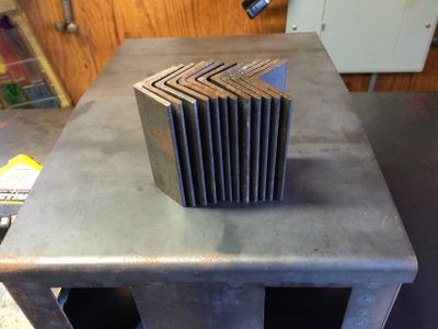
A complete set of welded steps.
A newly installed step.
View of the step from the underside, showing where the step is welded to the frame. Not very pretty, but it is strong and, luckily, will not be seen by the typical observer.
I chose to weld the step on two sides, namely, the side of the car and underneath the floor. It is not welded to the bumper.
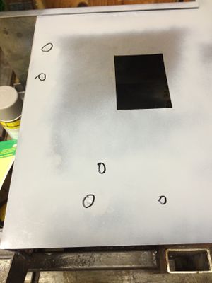
A coat of primer is sprayed on the side to identify dimples from welding that must be filled in. The dimples are circled.
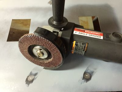
Two of the dimples have been prepared for filling.
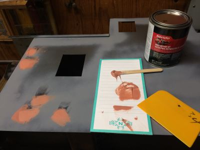
The dimples have been filled with "Bondo". Once set, the filled dimples will be sanded smooth.


Battery Box
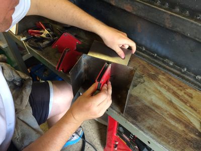
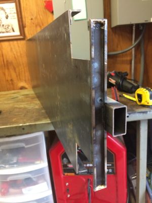
I decided to model the caboose after the Santa Fe caboose #999187 located at the Comanche & Indian Gap Railroad railroad. I needed a battery box in place of the tool cellar. Here my nephew Stephen is setting up to weld the box together. Note that this battery box was built from scratch, and is not part of the Kitsap Live Steamer's kit.
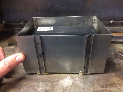
The dimensions of the box is 6-1/2 inches deep, 4-1/2 inches deep, and 3-3/4 inches high. After installation on the chassis the box looked a bit over-sized, so you may need to adjust for your taste. The battery box is large enough to hold a standard gel-cell battery. The battery will power the lights on the caboose. The two front braces were cut from 1/2 inch square steel tubing. It is cut down to about 1/8 inch high, so that the side ribs show prominently like the prototype.
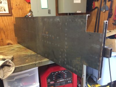
Here you can see the filler welds that hold the front braces onto the faceplate. Holes were drilled in the faceplate, the braces were clamped onto the faceplate, and the holes were filled with welds from the backside of the faceplate. The welds were ground down flat.
The box was welded together using "stitch" welds to prevent warping.
The top back mounting brace is welded onto the battery box.
The front brace is welded in place. Other components shown here include the terminal strip and the fuse holder.
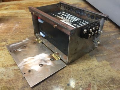
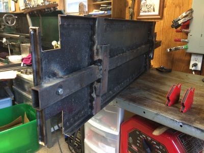
The terminal strip and fuse holder have been mounted on the side of the battery box. I made a mistake here, in that I mounted the terminal strip on the side where the air tank will reside. Not much access room after the battery box and air tank are mounted next to each other.
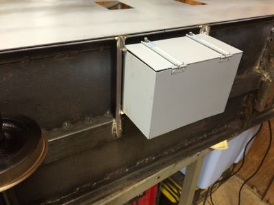
The battery box has been welded onto the caboose chassis. The mounting brackets are 1/2 by 1/2 inch angle steel.


