Turning an Eccentric Hole in a 3-Jaw Chuck
by Ron Thibault
You can turn an offset (eccentric) hole in a workpiece using only a 3-jaw chuck. You insert a block between the workpiece and one jaw, then clamp.
Theory
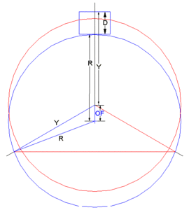
Figure 1 shows the concept. The red circle represents the workpiece clamped normally with its center on the chuck centerline (the three 120 deg apart lines). The blue circle represents the workpiece with block D clamped in one jaw (with the total assembly center on the chuck centerline). This gives an offset for the workpiece itself of OF.
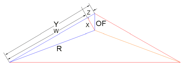
To calculate the size of the Block D needed to get Offset OF the triangles shown in Figure 1 are further broken down as shown in Figure 2. The angle between lines Z and OF is 60 degrees. The following values are defined:
- In Figure 1:
- D = Length of the Block
- OF = Offset of Workpiece
- R = Radius of Workpiece
- Y = Effective Radius of Block/Workpiece assembly
- In Figure 2:
- Z = OF * cos(60)
- X = OF * sin(60)
- R2 = X2 + W2
- Thus:
- W2 = Square Root(R2 - X2)
- Y = W + Z
- D = Y - R + OF
- D = W + Z - R + OF
- D = Square Root(R2 - X2) + Z - R -OF
- D = Square Root(R2 - (OF * sin(60))2) + (OF *cos(60)) - R + OF
- D = Square Root(R2 - (OF * sin(60))2) + 1.5OF - R
Example
As an example (using the eccentrics for Minnie):
- For:
- R = 1.6875 inches
- OF = 0.313 inches
- D = 0.448 inches
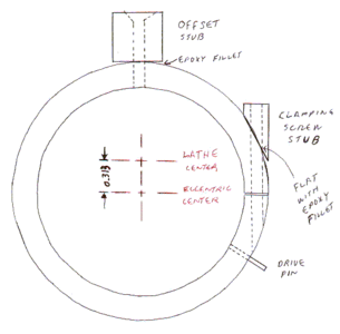
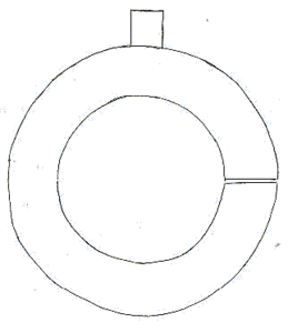
Two different styles of jig are shown in Figures 3 & 4. The jig in Figure 3 is more for a large production run. The workpiece is clamped into the jig with the clamping screw and then secured in the chuck. This allows you to remove the jig and clamp the blank on the workbench. The jig in Figure 4 holds the blank using the clamping pressure of the chuck jaws. This requires that everything be assembled in the chuck, not a terribly difficult task. More clamping force will be needed by the chuck jaws than for the first jig. Jig 4 is much simpler to build though. It is assumed that the offset block for the second jig is secured to the jig body. You can also dispense with the jig and just use a block between the blank and one jaw, but be careful as this would not be as "solid" a clamping method!
Use the calculations shown above for the size of the offset stub needed to offset the jig the desired amount. Remember that the workpiece size used should be the OD of the jig ring, not the OD of the eccentric blank!
Constructing the jig
The rest of the write-up assumes that the jig in Figure 3 is being used.
Center drill, drill and bore the jig to the 2.125 inch dimension (Figure 3), or the final diameter of the eccentric bearing surfaces. Bore 0.001 inch oversize so that the eccentrics will just slide in. Mark the location of jaw #1 before removing the jig.
Make the jig offset stub per the drawing in Figures 3 & 4. The length is a critical dimension, it will determine the final offset in the eccentrics. A slight difference in the final offset is all right, but the closer the better. Drill the countersunk center hole (tap size for now) while the part is still in the lathe.
Place the jig in the chuck, with the offset stub between jaw #1 and the jig body. Use a drop of superglue to secure the stub. Remove the jig and carefully drill through the jig body using the hole in the stub as a guide, and clearance drill the hole in the stub with a #10 drill. Separate the stub and jig body, and clean off the superglue residue. Tap and debur the hole in the jig body 10-32. Mix some epoxy and use it between the stub and jig body to fill in the gap between the flat stub bottom and curved jig body. Keep the epoxy away from the immediate contact areas. Epoxy between those areas will throw off the stub length to body diameter geometry, and change the final offset of the eccentrics. If you coat the stub with oil or petroleum jelly the stub can be separated to allow the jig to be reused with different stubs, in the future. Clamp the two parts together with a flat head 10-32 screw. Using a piece of wax paper between the parts and the #1 jaw, chuck the assembly, and leave it until the epoxy has cured. Mark the location for the drive pin, while the part is still in the chuck. Drill with the correct size bit to mark the hole, using a piece of thin shimstock to protect the side of the jaw and the chuck face. Drill for the pin after the piece is removed. Install and secure the pin with Loc-Tite.
When the epoxy is cured remove the assembly, and drill (tap size) the rim of the jig for the 10-32 clamping screw. Drill (tap size) a piece of round stock for the clamping screw stub on the lathe and cut it off at the needed angle, as determined by using a dowel, pin, or a drill bit as a guide. File a partial matching flat on the jig and attach the stub with more epoxy. You may wish to tap the jig and use a screw to hold the stub in place. Once the epoxy is set cut the slot in the jig body. Drill the stub side of the body with a #10 clearance drill. Instead of using a stub for the clamping screw a flat could have been milled for the screw head.
Using the jig
Clamp, loosely, the jig back in the lathe (offset stub at jaw #1 and drive pin at jaw #3). Install an eccentric (collar side out) and tighten the clamping screw and then the chuck jaws, to secure the part. Drill, bore, and ream for the axle hole. Turn down the collar and spine areas per the drawing.
Repeat for the other eccentrics. The final step is to drill and tap the collar (per the drawing) for the two setscrews (Figure 21). The two setscrew holes are set 90 degrees apart, to properly secure the part once on the axle.


