Machining Lubricator Ratchet Wheels
Posted by Carrdo on Chaski.org, 6 March 2003

I have a number of the mechanical type lubricators of the typical LBSC type as shown in the first photo. Properly constructed, I have found them to be very durable and reliable. One of the Hudsons I have has one of these lubricators which had over 30 years of running before I acquired it. The lubricator still works even though the ratchet wheel has been completely worn down on one side through use - the ratchet wheel itself now looks like a bevel gear with no pawl engagement on the one side of the ratchet but the lubricator still pumps oil.
The double pawls themselves are in perfect condition but the lubricator swing arm holes have worn badly and the spring wire return springs need renewal. So, time for a rebuild. In addition,there are a number of other lubricators with missing parts in the shop so why not add this to the project.
LBSC himself never gave any instructions in his designs (to my knowledge) on ratchet wheel construction although he often said he could. When he came to this part he wrote that they were cheaply available from any local live steam supplier.
I guess this may have been true at the time but the standard LBSC lubricator ratchet wheel has all but disappeared here in North America. Most advertisers sell complete lubricator units but few spare parts.
Five extra wheels would probably last a lifetime, so that was the batch lot I decided should be made.
The standard LBSC lubricator ratchet wheel which was used in all of his 3/4" scale locomotive lubricators is 7/16" OD, 3/32" thick, has 35 teeth and has a 3/32" dia. mounting hole in the center.Typically, constructors have made these wheels from oil hardening drill rod, 01 machinery steel or gauge stock which is machined in the unhardened state and then hardened and tempered.
35 teeth seems a strange number, perhaps derived from experience and experimentation. 360 degrees divided by 35 is 10.3 degrees per tooth, a division not easily achieved in a home shop. Numerous articles have been published over the years with lubricators having both fewer and more teeth to pump more or less oil depending upon running experience and personal preference.
I ended up with 36 teeth as 360 divided by 36 is 10 degrees per tooth, a number my dividing equipment can easily handle and still be in the LBSC range.
For those of you who want to delve a little deeper into ratchet design, I have included the second photo. There are basically only four ways a ratchet system can work and this covers both external and internal ratchets. The pawl will either push the ratchet wheel (which is the LBSC and the general model lubricator design utilizing ratchets) or the pawl will pull the ratchet wheel or the ratchet wheel will push or pull the pawl. "Push" and "pull" are not the same - different design conditions have to be met in each case.
The case for the pawl pushing the ratchet wheel or the ratchet wheel pushing the pawl is shown in the second photo. It should be noted also that the teeth on the ratchet have to be oriented in a specific direction for the system to work properly. LBSC also writes that the operation of the swing arm should be such that it tends to tighten the ratchet on the shaft.

A ratchet wheel, in order for the pawl to lock positively onto every ratchet tooth, should have what is known as an "undercut". Undercut is achieved when the angle that a ratchet tooth subtends at its root is less than 90 degrees. Anywhere from 45 degrees through to 80 degrees have been used in industrial applications but 60 degrees is commonly found in model ratchets.
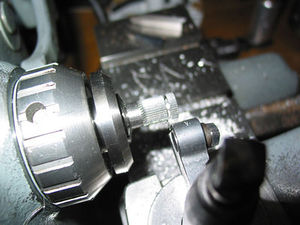
I made it easy on myself through the purchase of a small, 60 degree HSS (cobalt) dovetail cutter (a recognized brand) shown in the third photo. These are not exactly cheap but if one watches the ebay sales, they do come up at considerably reduced prices.
On the model lubricator ratchets of the LBSC design, one can see the angle which the pawls subtends at their tips is less than the ratchet tooth root angle (say 40-50 degrees). Needless to say the pawls themselves are hardened.

With the setup shown to the left one can machine the center hole either before or after cutting the ratchet teeth.
To do this the drill rod blank is held in a 7/16" collet in the lathe, end faced, carefully center drilled with a small center drill, under size drilled and then finished sized with a 3/32" dia. solid carbide reamer. I had planned on machining all five wheels at one setup but I cut this down to three and two to limit the depth of drilling with these small drills so as to keep the center hole truly concentric. One also has to allow for parting off and face cleanup metal loss on the center hole drilling depth.
The first question one has to answer is what depth of tooth will give the required number of teeth without leaving a land between the teeth or leaving the wheel machined under size? (on some commercially cut wheels, I noticed there was a small land left between teeth but whether this was intentional or not...).
Fortunately, Kozo, in his 3/4" scale construction articles and our own GWDriver, on another web site, gives the tooth depth as 0.014" - 0.015" for about the same diameter wheel with about the same number of teeth. This gives us a good starting point. As one proceeds, one can also advance the cutter in small increments until the land between each tooth just disappears. One needs good lighting, a sharp cutter and an eye loupe for this.
The dovetail cutter has to be set at the exact center line height of the stock held in the spindle of the dividing head. I used a vernier height gauge, a vee block set on its end, an adjustable parallel and a piece of cigarette paper to set the height of the cutter. The cigarette paper trick was also used to pick up the diameter of the stock. I can supply a photo if anyone needs it.
To do the dividing, a semi universal B&S type dividing head was used. I have never actually had to do indirect indexing before but after reading the instructions which came with the unit and a few trial passes cutting air, it all became clear and easy (one just has to follow exactly the same steps on each and every division). I don't have to mention that the dividing head has to be set square and parallel with this setup.
After just kissing the periphery of the blank with the cutter, the cutter was in fed into the work 0.007" indexed 360 degrees, in fed another 0.004", indexed and finally in fed another 0.002" as this was when the land just disappeared in my case. Use lots of cutting oil.
The toothed blanks were then cut off with a small parting tool as shown in the 2nd photo.
The blanks were then setup in the surface grinder for grinding to thickness. One has to employ blocking pieces with cutouts to hold the wheels as I do not have a fine pole magnetic chuck to securely hold such thin parts. The cutouts on the blocking pieces are necessary even when taking light grinding passes, as the grinding action will cause the wheels to spin ( and mar the tooth edges) if blocked between straight edges.
That's basically it. The wheels still have to be hardened and tempered but nothing special here to show. I have left a few thou. oversize on thickness which will be ground out after hardening if there is any residual warping from the heat treating.
Parting off a ratchet wheel.
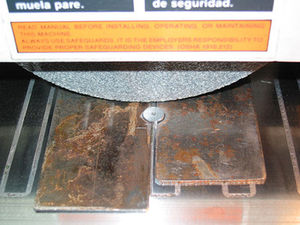
Grinding to finished thickness.
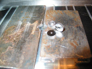
Three finished ratchet wheels
Worn ratchet.
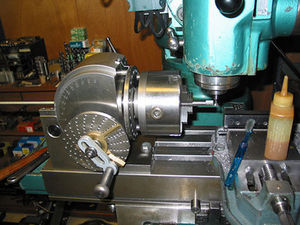
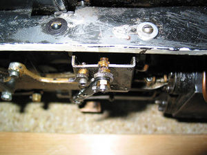
Overall view of indexing setup for cutting teeth on ratchet wheels.


