Loading gauge: Difference between revisions
Jump to navigation
Jump to search
| Line 18: | Line 18: | ||
|- | |- | ||
|Passenger Clearance Width-AA | |Passenger Clearance Width-AA | ||
|Foot Bar Clearance Width-BB | |||
|Engine Overall Width-CC | |Engine Overall Width-CC | ||
|Track Clearance Width-DD | |Track Clearance Width-DD | ||
|Passenger Clearance Height-EE | |Passenger Clearance Height-EE | ||
|Foot Bar Clearance-GG | |Foot Bar Clearance Height-GG | ||
|Track Clearance Height-HH | |Track Clearance Height-HH | ||
|Tunnel Head Clearance Radius-II | |Tunnel Head Clearance Radius-II | ||
|- | |- | ||
|6 | |6 | ||
| | |||
|6 | |6 | ||
| | | | ||
| Line 34: | Line 36: | ||
|- | |- | ||
|30 | |30 | ||
| | |||
|10 | |10 | ||
|10 | |10 | ||
| Line 42: | Line 45: | ||
|- | |- | ||
|30 | |30 | ||
| | |||
|12 | |12 | ||
|12 | |12 | ||
| Line 50: | Line 54: | ||
|- | |- | ||
|36 | |36 | ||
| | |||
|18 | |18 | ||
|15 | |15 | ||
| Line 58: | Line 63: | ||
|- | |- | ||
|48 | |48 | ||
| | |||
|36 | |36 | ||
|30 | |30 | ||
| Line 66: | Line 72: | ||
|- | |- | ||
|48 | |48 | ||
| | |||
|36 | |36 | ||
|30 | |30 | ||
Revision as of 11:13, 4 May 2017
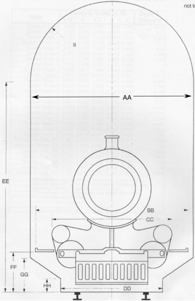
A loading gauge defines the maximum height and width for railway vehicles and their loads to ensure safe passage through bridges, tunnels and other structures. In the case of live steam operation, the Loading gauge must include clearances for passengers.
MiniRail Standard
The following Loading gauge was published by Mini-Rail Corporation in the late 1980's. The IBLS does not presently provide a Loading gauge standard.
| 1/2 inch scale | 3/4 inch scale | 1 inch scale | 1.5 inch scale | 3 inch scale | 5 inch scale | ||
|---|---|---|---|---|---|---|---|
| Passenger Clearance Width-AA | Foot Bar Clearance Width-BB | Engine Overall Width-CC | Track Clearance Width-DD | Passenger Clearance Height-EE | Foot Bar Clearance Height-GG | Track Clearance Height-HH | Tunnel Head Clearance Radius-II |
| 6 | 6 | ||||||
| 30 | 10 | 10 | 48 | 1 | 0 | 14 | |
| 30 | 12 | 12 | 48 | 2 | 0 | 14 | |
| 36 | 18 | 15 | 48 | 4 | 2 | 18 | |
| 48 | 36 | 30 | 60 | 10 | 4 | 24 | |
| 48 | 36 | 30 | 60 | 10 | 4 | 24 |

Mini-Rail Corporation Loading gauge