Durkee Hydraulic Engine Lift
The North American Live Steamer, Number 1 Volume 4

A growing inch and a half scale engine, like a growing calf, one day reaches the stage where it just can't be lifted any more. Such was the case in my shop where our 4-4-0 was provoking more and louder grunts and groans as it was wrestled up and down from its erection track and on out to our running track in the yard. Each new part made it more apparent something would have to be done, and soon.
A number of solutions to the problem presented themselves, but were discarded for one reason or another. Finally, a bit of pure inspiration plus finding suitable material evolved the hydraulic lift we now have. And it literally almost fell together. Compared to build a locomotive, that is!
The biggest obstacle in building such a lift is the long cylinder and ram required. One day while looking through a scrap yard I ran across some seamless steel tubing in a number of sizes and weights. No information was available as to what the material was exactly, but it machined like mild steel and has a finish not unlike cold rolled. I've subsequently found out that similar seamless tubing is available in larger steel warehouses and you can get just about anything you want from plain tubing like mine to the highly finished, but expensive Shelby tubing.
To start with, you have to do a bit of figuring. What size cylinder and what size ram you need. Of course, availability of material has something to do with it, but you've also got to consider the size and weight of your engine and the height you'd like to lift it. Various formulae for figuring column are helpful in a case like this, but you can let common sense and the plain arithmetic of hydraulics do most of the job.
I used a two and one eighth inch ram and a two and a quarter inch cylinder. This has worked out very well for my engine and tender which weigh about three hundred and fifty pounds. With a ram five feet long I can safely raise the engine some four feet above the floor which is ideal for maintenance and cleaning under the chassis.
Construction might well begin with the cylinder. Weld or braze a cap to the bottom, making sure of an oil-tight joint. Provide an opening for the oil line at the bottom by tapping the cylinder wall or weld a fitting in place.
The top of the cylinder is finished with a flange or ring an inch or so greater in diameter than the cylinder and with about six half-inch studs to hold the ram guide plate in place. I found that the studs alone are enough to hold the guide plate, but you could turn a recess in the flange and a projection in the guide plate to fir it if you wanted a deluxe job.
Chamfer the top edge of the cylinder. It will help in getting the cup leathers which form the oil seal of the piston in place during assembly.
The ram is just about as simple. Turn a piston to fit the cylinder. Drill and tap it for a bolt to hold the cup leathers and turn the other end to a shrink fit in the ram tube. Heat one end of the tube and the piston will fit in place easily for a permanent assembly. Provide some means of locking the bolt from turning or it will loosen in time as the lift is turned in use. A simple set screw is all that's needed.
Cup leathers as used in water pumps, etc., are available in almost any size you'll need and are available from pump supply firms or the larger hardware outlets. I used two of them and they're separated by a thick washer turned to fit. It's well to make another washer for the bottom leather to unsure that the edge of the leather will not rest on the bottom of the cylinder should you ever retract the ram fully.
The ram guide plate at the top of the cylinder is bored for a sliding fit with the ram and is drilled to take the studs in the flange at the top of the cylinder.
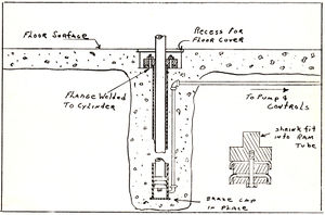
With this much done, you're ready for some assembly work. This will depend much on where you're going to put your lift, and the type of floor you have to contend with. I located my lift at one end of the shop near an outside door so that we can run the engine out via a channel iron bridge from the lift to a spur to the shop.
Our shop floor is concrete and so the first order of business was to knock a hole in the floor. Then I used a post hole digger to sink a vertical hole about six inches in diameter and about six feet down. I didn't want to tear up the floor any more than necessary so I drilled a horizontal hole in from outside the shop to take the oil line. This was pretty easily done with an old wood bit welded to a long rod. It was just a matter of taking aim, and hoping for the best while boring away with the long bit in the business end of a carpenter's brace.
To place the cylinder I found it best to assemble the piston, ram and guide plate, etc., in the cylinder. This was then blocked about half way out so that the protruding ram might be used as a reference for getting the cylinder plumb. Naturally the pipe line has to be connected up as you set the cylinder. The horizontal line can wait until the cylinder is partially set. Be careful of your joints, or they're permanently buried.
I used a fairly rich mixture of concrete and packed it firmly around the cylinder; checking it frequently to make sure it was perfectly plumb. I set the top of my cylinder several inches below the floor surface so that the ram could be retracted and covered with a floor plate in a recess provided for it. So far I've not used this feature, but it's there if we ever need a completely unobstructed floor.
The top end of the ram is fitted with a head consisting of a couple of spacing blocks with channel iron rails bolted to each side. I made a pattern and had a couple of iron castings made, but you could use heavy iron plate (say an inch or so thick) if you want to go to the work of cutting it out. Or, if your engine is small, you might try using hardwood blocks. The photos show how the rails and castings clamp to the ram. My rails are six feet long and are of two inch channel iron. Larger or smaller rails can of course be used depending on your engines.
The next item to consider is the pump and control valves. You can use almost anything - from a hand pump to a motor driven affair like mine. I happened to have a pump and gear motor on hand and these assembled easily into a compact unit on top of a reservoir made of a length of six inch pipe with iron plates brazed on the ends.
Actually the only control you need is a valve to release the oil from the cylinder to the reservoir. And, of course, a switch to turn on your pump motor. If you do use a power pump you should make some provision that the pump can't be inadvertently left running and the system wrecked when the ram reaches its top limit. A pressure relief valve, or (like mine) a momentary contact switch which has to be held closed to operate the motor will do the job.
I used one eighth inch pipe for all my lines because I had quite a few of that size fittings on hand. With light weight mineral oil in the system this size is O.K. Larger pipe would give a little faster action on lowering the empty lift but this happens so seldom that it's not worth considering.
Simple contact switch operated by left hand-wheel starts motor. The right is the release valve. Toggle switch shuts off power to panel indicated by pilot light.
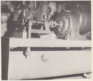
Simple contact switch operated by left hand-wheel starts motor. The right is the release valve. Toggle switch shuts off power to panel indicated by pilot light.Motor and pump mounted on oil reservoir are out of the way under bench. Check valves prevent oil leak-back through pump.
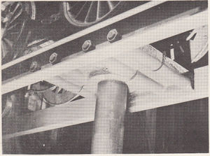
Rails and castings are clamped to top of ram by 4-1/2 inch rods nutted on each end.
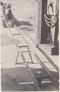
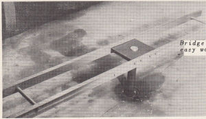
Bridge between lift and track spur makes easy work getting engine out on main line.