Dead center: Difference between revisions
(→Videos) |
|||
| Line 43: | Line 43: | ||
* [http://www.discoverlivesteam.com/magazine/07/07.html "Finding Locomotive "Dead Centers", <i>DiscoverLiveSteam.com</i>] | * [http://www.discoverlivesteam.com/magazine/07/07.html "Finding Locomotive "Dead Centers", <i>DiscoverLiveSteam.com</i>] | ||
* [ | * [https://www.jghtech.com/assets/applets/LFLSRM-Finding-Dead-Centers-current.pdf "Finding Locomotive Dead Centers", Jeffrey G. Hook] | ||
Revision as of 13:11, 8 February 2019
From Frank Williams, Locomotive Valve Setting, 1944:
- A locomotive is said to be on a dead center when the center of the main axle, the main crankpin, and the wristpin in the crosshead fall in one straight line. In a locomotive with two cylinders and the cranks set at right angles to each other, there are naturally four positions in which this condition is met. Then the dead centers, taken in order through one complete revolution of the main wheels, are the right front dead center, left front dead-center, right back dead center, and left back dead center.
Finding Dead Centers
The Live Steamer, January-February 1950
For some reason, there always seems to be, among many of the builders of our small locomotives, a certain amount of mystery about what is meant by the term "Dead Centers" and why they are important in correct valve setting and in the testing of the radial valve-gears. The three commonly used radial gears in this country are the Baker, Walschaert and Southern.
It is absolutely essential that we know where the "Dead Centers" are located, in order to set the valves so that they will give equal Lead on both front and back dead center. The manner in which this is done is taken from The Locomotive Up to Date by McShane.
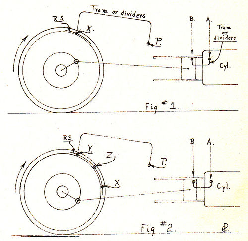
For the sake of convenience we shall first find the right forward, or front dead center. The method of finding this is as follows. With the driving wheel connected to the crosshead, move the crank forward by revolving the drive-wheel until the crosshead reaches a point about 1/8th inch from the end of its stroke, as shown in Figure #1.
With a crosshead tram set on the point A, on the front guide block, scribe an arch B, on the crosshead, to mark this position. At the same time and without changing the position of the crosshead, from a convenient stationary point on the frame, such as point P, scribe an arc X on the face of the tire. Continue to revolve the wheel as indicated by the arrow, until the crosshead passes the end of its stroke and begins its backward movement, stopping it when the tram previously used, reaches exactly from the point A on the guide, to the point B on the crosshead as shown in Figure #2.
Then re-tram from the point P to the tire using the same tram as in Figure #1, and with the wheel tram set at the point P, scribe another arc Y on the face of the tire as shown in Figure #2.
Now with a pair of Hermaphrodite calipers set about one half the thickness of the tire, draw a line RS parallel to the wearing face of the tire so as to cross both of the arcs made by the wheel tram at the points X and Y. With a pair of dividers carefully bisect the line RS between the points X and Y and scribe the center punch the exact center between X and Y as shown at Z. This point is the dead center mark, and the engine crank is at right front "dead center" when the wheel is revolved until the wheel tram reaches exactly from the point Z to point P.
Both front and back "dead center" positions must be determined in the same way, except that when locating the back centers, the crosshead tram is used from the back guide block, or rear end of the guide. The effect of measuring on the crosshead is to find a point where the crosshead travel (from the end of the stroke) is the same, both when approaching, and when leaving the end of the stroke. By transferring these points to the driving wheel and dividing them to find the central point, the actual end of the stroke, or "dead center" is determined absolutely.
The four important points on the stroke are now definitely located on the wheel, and are ready to be used for valve setting. In order to be able to test the correctness of the outside radial valve-gears and to set the valves properly, it is necessary to know exactly where all four "dead centers" are located.
I recommended that valves be set to give equal Lead at each end of the cylinder, when the piston is on its "dead centers" and the reverse lever in mid-gear. This allows the engine to be "hooked up" after it gets the load rolling, without having it go out of square. To do this you have to know exactly where the "dead centers" are.
Videos
<videoflash>E2XdFUt8sqI</videoflash>
