Colorado Central Flat Car in 1 Inch Scale
Colorado Central Flat Car in 1 Inch Scale
by R.B. Bagley
Southern California Live Steamers
The Miniature Locomotive, September-October 1953
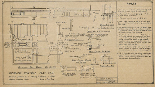
The car under frame is a one piece duralumin casting. Use of this metal keeps the cars light and easy to handle. Although the casting is large, it is perhaps the easiest one to finish. First remove all flashing and large bumps with a chisel and coarse (vixon) file. A 6 inch sanding disc in an electric drill is all that is needed to clean the top and sides. Be careful to keep the top and sides. Be careful to keep the flat surfaces true and even. If you have a milling machine and lots of time the sides and ends can be milled, but that is hardly necessary.
The three cored holes in each end of the frame hardly need explanation. The drawing shows clearly what they are for and when the flashing has been removed they should be ready for use.
A special tool will be needed to machine the bolster fit. A suggestion is given on the drawing. Cold rolled steel will be good enough for this tool as chances are that it will only be used to build a few cards for your own road. This tool is to be used in the drill press. Drill the hole in the car frame for the bolster pin with a No. 11 bit to give the 3/16 inch pin plenty of freedom. The pin on the end of the bolster cutting tool will guide the tool by means of this hole. Be careful to set it for the proper depth so that coupler height will be maintained correct. You will notice that only one dimension for depth is given on the drawing. That is the important surface which determines car height. The other surfaces should be cut deep enough to be clear of the bolster at all times.
The bolster side bearings have a metal wear plate attached. Although I have a milling machine, I usually do the job in my drill press because it is faster. Place the car frame on the drill press table bottom side up and block up with wood blocks under the extending portion. With a small end mill in the drill chuck and the spindle clamped tight, the pads can be faced by a few passes under the cutter. Clamping or guides are not necessary. Simply push the frame by hand, but keep a firm grip!
It is important that the principal weight be carried at the center bolster and not on the side bearings. They are for stabilizing only and should have 0.008 inch clearance when the car is sitting level. More clearance will cause the car to rock excessively and less may cause derailment on curves.
Striking plates, poling pockets and stake pockets are next. They only need clean up and to be drilled for rivets. Use 1/16 inch brass rivets or escutcheon pins throughout. In places where they cannot be headed both sides drill clearance holes as usual and then flatten the riven shank slightly in the vise. This will cause them to press in tight and they can be driven without danger of bending. One rivet between each rib on the striking plates and stake pockets is sufficient. Three rivets equally spaced, as shown on the drawing, at each end of the poling pocket will do for that. There is no standard for spacing or number of stake pockets. Each flat car may be different in this respect and spacing need not be regular.
Hard wood planking is best for the car floor as it will receive considerable wear and abuse. Fasten the planks with three drive pins to each plank. A hole should be cut in the planking to permit removal of the bolster pin. Various width of plank may be used on different cars, but care should be used to follow standard board sizes. Thickness of planks is generally 3 inches on big cars. Something slightly less than 1/4 inch will be correct in 1 inch scale. The reason for cutting undersize is to give better appearance. Boards are always smaller than the given size because they shrink after being cut in the mill.
The coupler is pretty well described on the drawing. The slot for the draft key may either be drilled and filled out or cut with an end mill. It should allow free movement of the key. The same is true for the slot in the draft yoke. The coupler pin is a simple lathe job. It should be made before filing the tail piece of the coupler knuckle so that the knuckle stop for open and closed position can be tested. The drawing shows a built up spring seat for the draft gear. Castings are now available for this part and save a great deal of time and work. The one marked "A" is used in the end next to the coupler shank. it is fascinating to ride the cars and watch the couplers move in and out as they take the shocks.
Small oblong stools 6 inches high and 8 inches by 12 inches on the seat are made to accommodate the live freight. Believe it or not, they will hold two people sitting back to back. Stools need not be fastened to the car. If the car is intended for use behind a 3/4 inch loco or smaller and to be ridden on a trestle stools will not be necessary.
