A Suggestion for Setting Out Walschaerts Gear
A Suggestion for Setting Out Walschaerts Gear
by LBSC
The Model Engineer, Volume 73, Number 1782, 4 July 1935
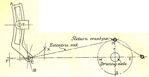
I guess you all know my pet way of "designing" a valve gear is to make up a dummy from bits of cardboard, bent tin and pins, so that I know exactly what the valve events are going to be on the finished engine. Very unscientific; but the funny part is that the engines always do the job, and like the famous productions of Mr. Henry Ford, the more they are derided, the better they seem to go! Now a brother who is building an engine and wished to fit Walschaerts gear, thought he'd have a go at the "scientific" method and see how the result compared with mine with especial reference to that "bone of contention," the offset of the link tail. So he cast his mind back to the elementary geometry lessons of his schoolboy days, and by aid of compasses and a rule, evolved the diagram reproduced. N.E.S.W. is a circle representing the travel of the return crankpin, the horizontal line passing through it is the centre line of motion. Step off the required length of eccentric rod with the compasses, and make arcs with the N.S.E.W. points as centres. This shows up clearly the error due to angularity of the rod, the forward swing being much the greater. Next put he point of the compasses on the centre line where the N and S arcs intersect, which is the position occupied by the eccentric-rod eye at half-stroke, when the piston should be on dead centre; then open the compasses until the pencil touches the point F, which represents the eccentric rod eye in full forward position. Strike a half-circle which cuts the other arc at a new point X. Now obviously the distance from C to F must be the same as from C to X. Join F and X and draw a line at right angles to it, which will pass through C. The link trunnion may be placed anywhere on this line; and if when it is vertical, the link tail eye is arranged to coincide with C, and equal swing each side of centre is obtained, no matter how short the eccentric rod is within reasonable limits. If the centre line of valve gear is above the cylinder centre line, as on some of the L.M.S. and Southern engines, it makes no difference to the procedure; all you do is to keep the link square with the centre-line of valve gear when in mid-position.
