A Simple Four Wheel Diesel
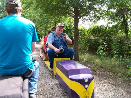
Back in 2012 I wanted to build a simple Diesel locomotive. I found a 4 wheel chassis from Ride Trains, and a wooden body from Mr Motion. The project was completed by adding battery trays, drive circuitry and lights. A great feature of the locomotive is that it is controlled using a low-cost Futaba radio controller. This allows operation from anywhere on the train. It also makes an excellent yard switcher. Its has proven to be an excellent puller for its size.
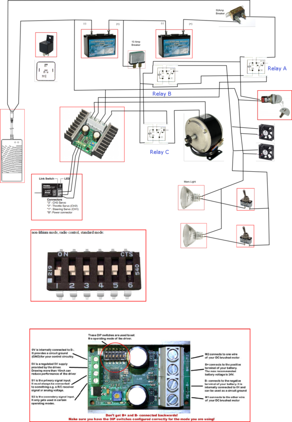
The wiring diagram is shown below as a starting point for others wishing to build a simple diesel.
Circuit Description
The 87A relays are designed for 12V systems. The contacts will handle 24V just fine, but the coil on the relay would burn out if energized with 24V, so we must have a 12V buss for energizing the relay coils. Also, we use the 12V buss to run the lights, fans, and any other 12V based accessories.
Lets look at the 12V buss first. The battery on the left supplies 12V for this buss. The positive side of the battery is protected by the 10 amp breaker. A line goes from the 10 amp breaker to one side of the coil of each relay. The other side of the three coils is wired to the input of the key switch. The key switch turns the whole system on or off through the relays. So the purpose of the relays is to connect/disconnect power from the 12v and 24v buses.
The output of the key switch is wired back to the negative side of the left battery, thus completing the energizing circuit for the three relays.
The 24V buss is used for the motor drive, and for no other purpose. The positive side of the right battery is fed to the 50amp breaker. Now this is a 12V 50 amp breaker meant for a car, but it has worked fine in the 24V system for several years for me. The output of the breaker goes to the contact of relay A. The other contact of relay A goes to the power input of the Syren50 controller. One leg of the motor drive output from the Syren50 controller goes to the contact of relay C and then to the motor. Therefore, relay C is controlling 0 to 24V, which is the variable output from the Syren50 controller.
Relay B controls the 12V buss for the accessories (lights, fans, etc).
The device on the left is an on-board 24V charger. Typically this is a 5amp scooter charger.
Schematic

Video
This video captured the first test of No. 4004's powered chassis.
