3-1/2 Inch Gauge Flat Car
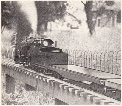
by George Taylor
The Model Craftsman, November 1945
Here's a well-designed Flat Car for that Live-Steam road. Complete details of Trucks, Wheels and Frame are given.
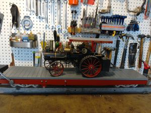
After you have your live-steam engine finished you'll need a flat-car to ride on, so here's one which not only looks fairly well but rides smoothly, too.
A flat-car looks quite a simple thing to build, yet if the proper principles are not properly applied you can have no end of trouble with it.
Description
One of the important things is to have a certain amount of flexibility in all the wheels, so that one wheel can rise over a bump or fall into a hollow in the track without affecting any of the other wheels.
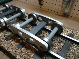
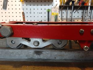
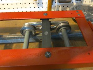
This flexibility must not only be applied to the trucks but must extend the full length of the car. The small trucks used in "O" gauge rolling stock for electric railroads embody an excellent way of making the trucks flexible; the truck sides are pivoted in the centre, on pins in the bolster, so that the sides can rotate. Thus, if you hold an assembled "O" gauge truck, with each hand grasping a side frame, each frame can be rotated in opposite directions to some degree; provided, of course, the holes for the axles are slightly larger than the axles. This excellent method of obtaining flexibility in the truck itself is used in these 3-1/2 inch gauge trucks also and works out very successfully.
However, this flexibility only takes care of the truck itself. It must be remembered that the trucks are pivoted at each end of a fairly stiff frame which cannot twist readily, and if one truck is on a level piece of track and the other is on a piece where one rail is lower than the other, then the wheels on the low rail side will not touch the rails, no matter how much flexibility is inherent in the trucks.
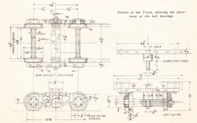
This condition can only be corrected in these cars by what we might call a "three-point suspension" -- that is, the front truck does not permit any rocking of the car sideways, whereas the rear truck is allowed to rock sideways and so can adjust itself to the irregularities of the track. This is accomplished by making the centre bearing of the front truck flat, with a little pad on each side for stability and is shown on the end view on the truck drawing. The centre bearing for the rear truck is made spherical and has no side-pads. The rear stretcher is shown above the end view of the truck.
It is important that the non-rocking truck be at the front under the driver; otherwise, if you are riding on the car alone and the rocking truck is underneath you, there is danger of tipping over.
The use of springs in these trucks -- following full-size practice -- is not very good procedure because the "pay" load on the car, compared with the weight of the car itself, is all out of proportion. Your weight can be shifted from side to side so quickly, depending on your movements on the car -- especially when going around curves -- that it becomes very uncomfortable and actually dangerous. It is better to have a positive stop in a lateral direction. If vibration damping is desired, it can be taken care of by stiff rubber pads placed under the platforms.
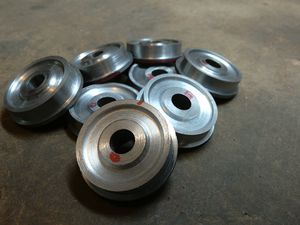
The second important thing is the use of ball bearings. This allows a little locomotive to pull about five times as much load than if plain bearings are used. The ball bearings should preferably be of the self aligning type to allow the necessary amount of flexibility to the truck sides. If these are not available, the next type of bearing is that which takes an end-thrust as well as a radial load and can be taken apart, something like a Timken bearing. However, if neither of these are available and the plain ball bearing has to be used, then the counterbore in the truck sides which carries the bearings will have to made about ".005 to .007" larger than the outside diameter of the bearing. The fit on the axle itself should be a light press fit.
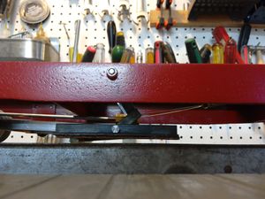
The third important thing is a good brake -- one that can stop on a dime! Having brake blocks on the wheels as in full-size practice is not much good and requires a lot of adjustment to make them work right. The best type of brake is one which presses down on the rail; this will stop you in one foot flat, and sometimes you have to stop like this. Well, so much for a general chaw on flat-cars.
Frame
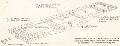
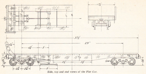
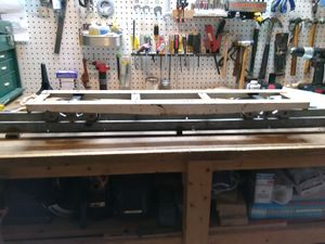
The logical place to start is the frame. This is built up of 1-3/4 x 1-3/4 x 1/8 inch and 1 x 1 x 1/8 inch angle iron. The perspective view shows the construction and the dimensions can be taken from the drawing of the car. Starting by cutting the angles to length and shape and assemble together with 1/4"-20 flat-head screws. You will have to countersink the holes in the angles so that the top of the flat-head screws will be flush with the surface to allow the wood floor to sit down on the frame. The end pieces are car-end castings supplied by Lester Friend (Yankee Machine Shop). These come with two lugs on the side which are cut off and the castings screwed to a piece of 1 x 1 inch angle-iron backing. One leg of the angle-iron is left as it is, while the other is cut to the shape of the car-end castings.
Trucks
The drawing showing the truck practically explains itself. The truck sides will have to be castings, of course, in either bronze or aluminum; both of these metals work well. The patter is a simple straightforward job and anybody who can build a locomotive can certainly make this pattern. If you can't swing the casting in your lathe to bore out the recesses for the ball bearings, then you'll have to do as I did. Centre-punch all the bosses, that is, those at each end of the bearings and the one in the centre for the bolster and drill with a 1/2 inch drill. Drill them in pairs back-to-back, so that the centre-to-centre distance on each truck will be the same. Next make a counter-bore as shown in the sketch; put the counterbore in the four-jaw chuck and be sure that it runs true. If you have a collet, so much the better. Then get a bar of [[CRS|cold-rolled steel] about the size of a tool-holder and clamp it in the toll-post, parallel with the lathe centre-line. Centre the 1/2<F2> inch hole (which you drilled in the truck casting for the bearings) on the end of the counterbore and bring the tail-stock chuck up against it. Open up the chuck so that the short end of the counterbore just runs freely inside the jaws. This steadies the end of the counterbore. Be sure that the inside face of the truck casting faces the counterbore. Now start the counterbore revolving, using the lowest speed on the lathe. Rest the free end of the casting on the piece of cold-rolled steel you clamped in the tool-post and start feeding in with the tail-stock. Take your time and don't rush this job; feed it very slowly. You can tell how far the counterbore has gone by watching the graduations on the tail-stock spindle. After all the recesses are bored for the ball bearings, face off the inside and ouside of the centre boss for the bolster.
Make the bolster out of a solid piece of cold-rolled steel 3/4 x 1 x 5-1/2 inches long, rather than drive in pins. Pins always have a nasty habit of working loose! The two bolts which hold the truck sides together are 1/4"-28 S.A.E.
Allow about 0.005 inch clearance under the washer so that the truck sides will be free to rotate on the bolster. The center hole for the pivot pin in the front bolster is 7/16 inch as shown, but the hole in the rear bolster (which has the spherical centre bearing) should be opened out to 1/2 inch diameter for a depth of 5/8 inch. This is to allow the bolster to rock. Be sure, when assembling, to have the 1/2 inch diameter opening downward.
Couplings
The couplings are bronze castings, which were also purchased. They are not "scale" couplings but are very efficient and all the boys at Danvers (Mass.) use them. It would be a good thing for all flat-cars to use this coupling, then they would all be standard and readily couple together when the occasion arose. The height from the rail top to the center of the coupling is 2-1/4 inch for a 3-1/2 inch gauge engine.
The couplings have a rectangular taper shank and can be used as they are. However, I turned down the shank to 3/8 inch diameter for a distance of 1-1/4 inch and drilled and tapped the end 10-32. This is done so that a spring can be used behind the coupling. It's nice to have this springy coupling because it gives the engine a better chance when starting a heavy load.
Brake
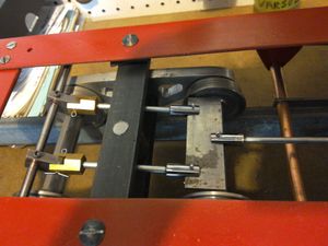
The brake is a regular piece of brake lining with a 1/8 inch steel plate back; it presses against the rail when the lever at the front of the car is pulled back. The drawing shows the arrangement clearly. The two front tie-rods should be made the same length, while the rear one should be made adjustable in length, so that the brake can be adjusted. The adjustment can be made similar to the old-style auto brake rods, that is, a forked end with a lock-nut. Two little springs--one in front and one in back of the brake shoe--will be required to bring the shoe up off the rails in a parallel position. And don't forget--the brake should be at the front of the car under the driver.
Platform
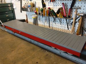
The platform is a piece of five-ply wood or a piece of hard wood, according to choice. It is 3/8 inch thick and is screwed to the frame with short wood-screws from underneath. Just be sure the screws don't go through the platform or there might be disastrous results when you get on and off the car.
2019 Version
Bob from Canada wrote, 27 April 2019:
I recently found the plans for the 3-1/2 Inch Gauge Flat Car. I found it interesting, as it could double as a riding car, and I needed one of those to tow behind my Rob Roy.
I worked on it over the winter and am just putting the finishing touches on it today. I'm not a machinist, so I found it challenging as well as rewarding.
Thank you for making the plans available. I'm sure the car will work perfectly this summer--and every one thereafter.
The local live steam club sold its riding car (or driving car, if you prefer), and I was left without something to tow around behind my Rob Roy. Accordingly, I decided to roll my own, so to speak.
I decided that I should be able to build the car with materials that I had on hand; I have therefore used bed rails found in the barn, a 2 1/8 inch round bar of steel left behind in my little garage by someone, a scrap piece of 3/8 inch aluminum plate, and numerous other odds and ends, including a punctured inner tube to make rubber vibration dampers between the trucks and the frame. I calculate that I have spent around $15.00 on it so far (had to buy wheel bearings and a bit of 1 x 1/2 inch steel bar), and shouldn't have to spend more, as all remaining materials are at hand and I have lots of leftover paint.
Wheel shoulder, flanges, and everything else follow George Taylor's plans. I wondered about the shoulder, thinking it perhaps should have been more pronounced, but the general opinion seems to be that coning the wheels is more significant for tracking. The design I used did not call for coned wheels, but I cut a 3 degree taper there, though it's hard to see over a 3/8 inch tread. Moreover, the track on which this is to be run is not one of those snazzy factory-made rail things, but 3/8 x 1 inch mild steel bar set on edge, and I think that the square shoulder will work better with it (there is a teensy little radius there to preserve strength). Flange depth may be a consideration if the car is to travel over frogs, points, etc., but my track is a simple oval, and I just don't see a wheel hopping up and down.
As you can see, I arrived at the wheel profile after a lot of mulling and reading, and I like to think that I've done the right thing here. Of course, if I haven't, I'll find out in May when I run this car. Even then, though, it won't be all that hard to re-shape the wheels if I have to (I hope).
As for the side frames, they will do the job, but I messed up on the symmetry of the outlines. It's not too easy to see when the frames are under the car, but trust me, they could be a lot better. I didn't re-do them both because they're hard to see and because they really did take a lot of time to make.
